
Protective structure of a highway bridge

A technology for protective structures and highway bridges, applied in bridges, bridge construction, bridge parts, etc., can solve the problems of large temperature difference, uneven road surface of highway bridges, and enlarged gaps, so as to avoid weathering, prolong service life, and achieve better protection effect. Effect

Inactive Publication Date: 2020-08-25
CHONGQING VOCATIONAL INST OF ENG
View PDF6 Cites 0 Cited by
  • Summary
  • Abstract
  • Description
  • Claims
  • Application Information

AI Technical Summary

Problems solved by technology

The design and planning of highway bridges need to consider many factors. In the construction of highway bridges in northern cities, it is necessary to consider the large temperature difference. The highway bridges are composed of multiple bridge slabs, and the deformation of multiple bridge slabs in the external environment is easy to cause The gap between two adjacent splices becomes larger, or the bridge slabs that are adjacent to each other are arched, resulting in uneven road surface of the highway bridge

Method used


Image

  • Protective structure of a highway bridge
  • Protective structure of a highway bridge

Examples


Embodiment 1

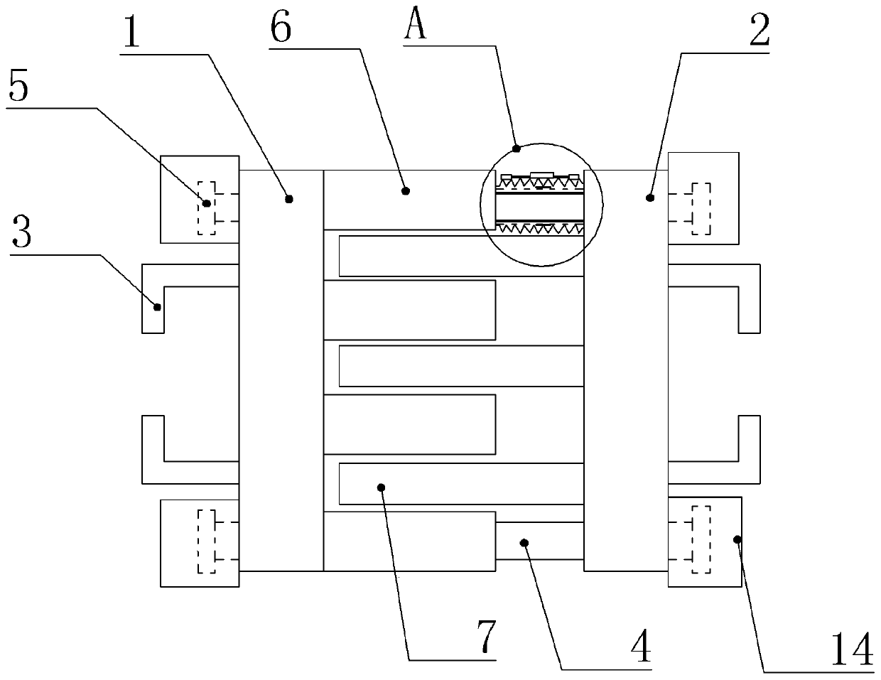
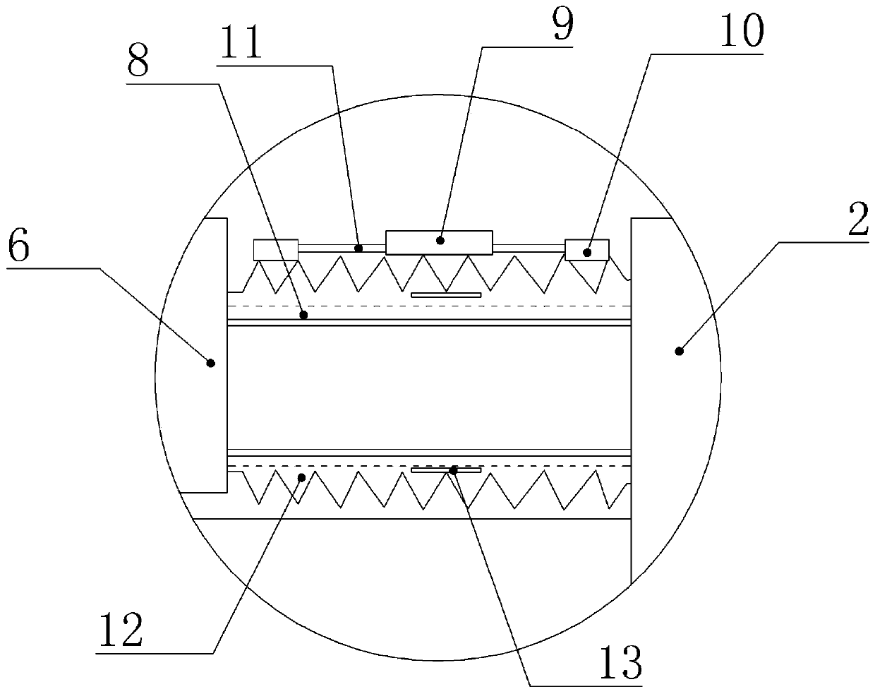
[0019] Such as figure 1 with figure 2 Shown: a protective structure of a highway bridge, including a first base 1 and a second base 2, the first base 1 and the second base 2 are vertically arranged, the first base 1 and the second base The upper ends of the bases 2 are flush, and the outer sides of the first base 1 and the second base 2 are provided with connecting parts. The connection part includes two L-shaped steel plates 3 , and the two L-shaped steel plates 3 are arranged symmetrically along the horizontal central axis of the first base 1 . The first base 1 and the second base 2 are slidably connected by a support rod 4, the upper end and the lower end of the first base 1 are provided with a first mounting hole, and the upper end and the lower end of the second base 2 are provided with a second mounting hole, The first installation hole and the second installation hole are oppositely arranged, the support rod 4 passes through the first installation hole and the second...

Embodiment 2

[0022] The difference between Embodiment 2 and Embodiment 1 is that the distance between the upper end surface of the elastic sleeve 8 and the upper end surface of the first base 1 is 2.3 cm, and this distance setting is suitable for roads where tourist vehicles in the field often travel. bridge pavement.

Embodiment 3

[0024] The difference between embodiment 3 and embodiment 1 is that the distance between the upper end surface of the elastic sleeve 8 and the upper end surface of the first base 1 is 3 cm, and this distance setting is suitable for highway bridge road surfaces where heavy-duty vehicles travel more. .

[0025] The specific implementation process is as follows: first, during the construction of the highway bridge, the L-shaped steel plate 3 and the bridge plate are fixed together, and the entire protective structure is placed at the gap between the two bridge plates. When the weather in the north becomes cold, the first base 1, the second base 2, the first splicing block 6 and the second splicing block 7 are all contracted by the cold, and the space between the first splicing block 6 and the second splicing block 7 Gap becomes bigger, and the length of elastic sleeve 8 becomes longer. Now, block 9 is also contracted by cold, because the degree of contraction of block 9 by cold ...


PUM


Abstract

The invention relates to the technical field of highway bridges, and discloses a protection structure of a highway bridge. The protection structure comprises a first base and a second base which are vertically arranged, the first base is slidingly connected with the second base through a supporting rod, multiple first splicing blocks are arranged on the side, close to the second base, of the firstbase, the first splicing blocks are mutually perpendicular to the first base, multiple second splicing blocks are arranged on the side, close to the first base, of the second base, the second splicing blocks and the first splicing blocks are staggered, an elastic sleeve sleeves the portion, located between the first splicing blocks and the second base, of the supporting rod, one end of the elastic sleeve is connected with the first splicing blocks, the other end of the elastic sleeve is connected with the second base, a wood block and two metal blocks which are arranged at intervals are fixedly connected to the upper end of the elastic sleeve, the wood block is located between the two metal blocks, and are connected with the metal blocks through an elastic strip. According to the protection structure of the highway bridge, a gap between two adjacent bridge plates is automatically adjusted, and the protection effect of the highway bridge is better.

Description

technical field [0001] The invention relates to the technical field of highway bridges, in particular to a protective structure for highway bridges. Background technique [0002] Highway and bridge engineering includes the main body of the bridge and the auxiliary engineering facilities in the overall bridge position. There are many affiliated engineering facilities, such as revetments to maintain the stability of the bridge at the river channel, diversion dikes and other structures to regulate water flow, approach bridges connecting the bridge head with the road, railings on the bridge surface to prevent wheel collisions, and sidewalks to ensure the safety of pedestrians Railings, as well as signs on the bridge, navigation signs under the bridge and bridge deck lighting equipment. The design and planning of highway bridges need to consider many factors. In the construction of highway bridges in northern cities, it is necessary to consider the large temperature difference. ...

Claims


Application Information

Patent Timeline
Patent Type & Authority Patents(China)
IPC IPC(8): E01D19/06
CPCE01D19/06
Inventor 李书芳刘霞
Owner CHONGQING VOCATIONAL INST OF ENG
Learn More