Phased array antenna for RFID system and RFID system

A phased array antenna and array antenna technology, applied in the electronic field, can solve problems such as mechanical wear and tear, and achieve the effect of improving service life and avoiding mechanical wear

Pending Publication Date: 2019-03-12
SHENZHEN AEROSPACE INNOTECH +1
View PDF0 Cites 0 Cited by
  • Summary
  • Abstract
  • Description
  • Claims
  • Application Information

AI Technical Summary

Problems solved by technology

[0004] However, the way of mechanical rotation needs to artificially rotate the direction of the antenna, as the number of rotations increases, it will cause mechanical wear

Method used


Image

  • Phased array antenna for RFID system and RFID system
  • Phased array antenna for RFID system and RFID system
  • Phased array antenna for RFID system and RFID system

Examples


Embodiment Construction

[0036] In order to make the purpose, features and advantages of the present application more obvious and understandable, the technical solutions in the embodiments of the present application will be clearly and completely described below in conjunction with the drawings in the embodiments of the present application. Obviously, the described The embodiments are only some of the embodiments of the present application, but not all of them. Based on the embodiments in this application, all other embodiments obtained by those skilled in the art without making creative efforts belong to the scope of protection of this application.

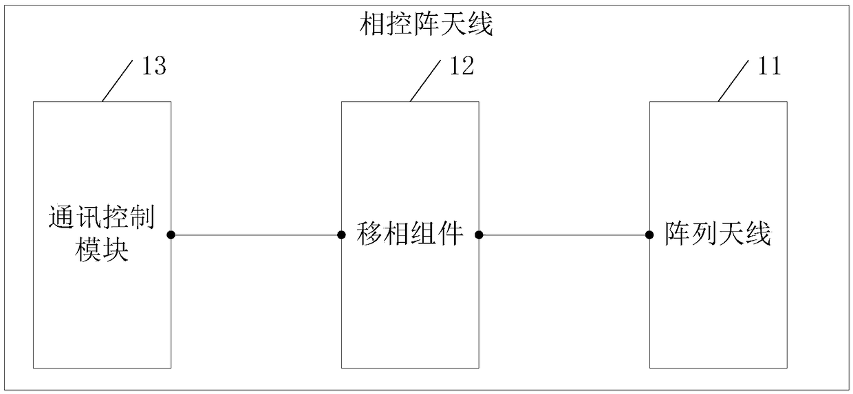
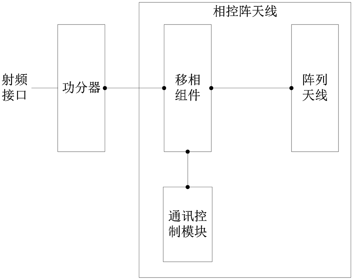
[0037] An embodiment of the present application provides a phased array antenna applied to an RFID system. see figure 1 , the phased array antenna includes:

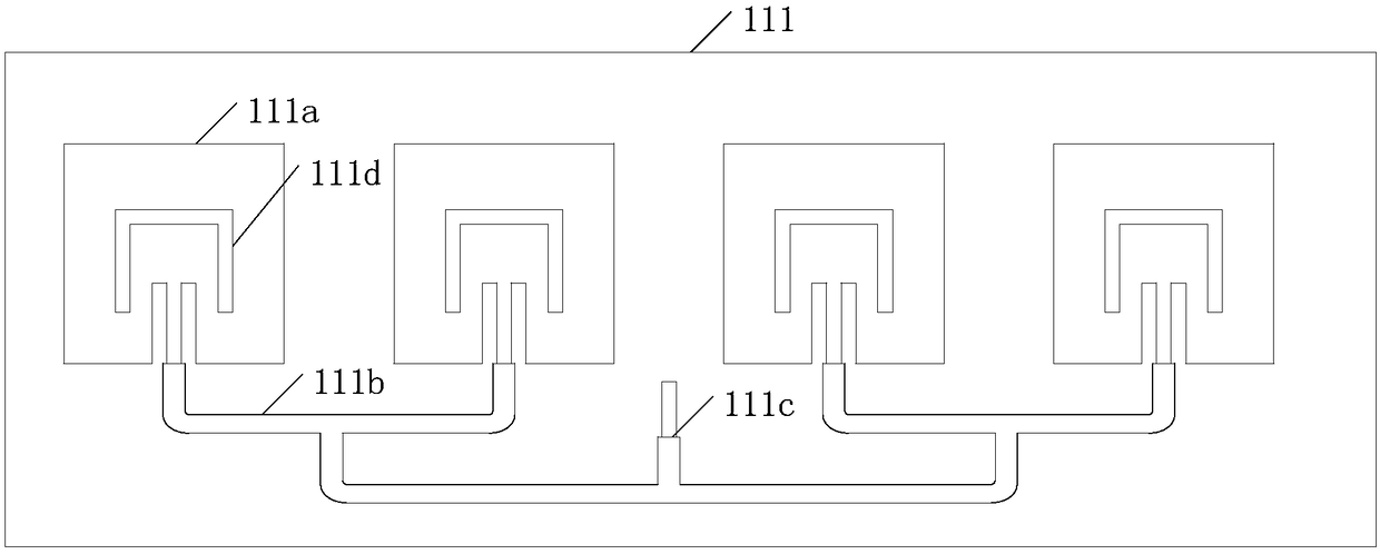
[0038] An integrated transceiver array antenna 11 composed of antenna sub-arrays;

[0039] And, the phase shifting component 12 electrically connected with the array antenna 11;

[0040] And, a...


PUM


Abstract

The present application provides a phased array antenna for an RFID and an RFID system. The phased array antenna includes a transceiver array antenna composed of antenna subarrays; a phase shifting component electrically connected to the array antenna; a communication control module electrically connected to the phase shifting component and having a phase shifting control function; and the phase shifting control function is a function of controlling a phase of each antenna in the array antenna by using the phase shifting component. Dynamic adjustment of a beam can be implemented in a solutionprovided in the present application.

Description

technical field [0001] The present application relates to the field of electronic technology, and in particular to a phased array antenna applied to an RFID system and the RFID system. Background technique [0002] Radio Frequency Identification (RFID) technology, also known as radio frequency identification, is a communication technology that can identify specific targets through radio signals and read and write related data. [0003] At present, the solution to realize the adjustable RFID communication area adopts mechanical rotation, that is, manually adjusts the radiation direction of the antenna to realize the movement of the antenna beam. [0004] However, the way of mechanical rotation needs to artificially rotate the direction of the antenna, which will cause mechanical wear as the number of rotations increases. Contents of the invention [0005] The present application provides a phased array antenna applied to an RFID system, which can realize dynamic adjustment...

Claims


Application Information

Patent Timeline
Patent Type & Authority Applications(China)
IPC IPC(8): H01Q23/00H01Q21/24H01Q1/22H01Q3/34
CPCH01Q23/00H01Q1/2208H01Q3/34H01Q21/24
Inventor 闫泽涛吴子勇冯汉炯杨正明于波
Owner SHENZHEN AEROSPACE INNOTECH
Why Eureka
Try Eureka