Hand and eye calibration method based on 3D vision

Inactive Publication Date: 2019-03-15
JIANGSU JICUI MICRO NANO AUTOMATION SYST & EQUIP TECH RES INST CO LTD
View PDF6 Cites 11 Cited by
  • Summary
  • Abstract
  • Description
  • Claims
  • Application Information

AI Technical Summary

Problems solved by technology

The shooting area of ​​3D vision sensor is limited. Large parts are usually collected in segments and reconstructed by data registration method. Although the target can be achieved, the accuracy is relatively low

Method used


Image

  • Hand and eye calibration method based on 3D vision
  • Hand and eye calibration method based on 3D vision
  • Hand and eye calibration method based on 3D vision

Examples


Embodiment Construction

[0017] The present invention will be further described below in conjunction with the accompanying drawings and specific embodiments, so that those skilled in the art can better understand the present invention and implement it, but the examples given are not intended to limit the present invention.

[0018] It can be understood that the following KUKA manipulators can also use other types of manipulators, and the present invention is not limited here.

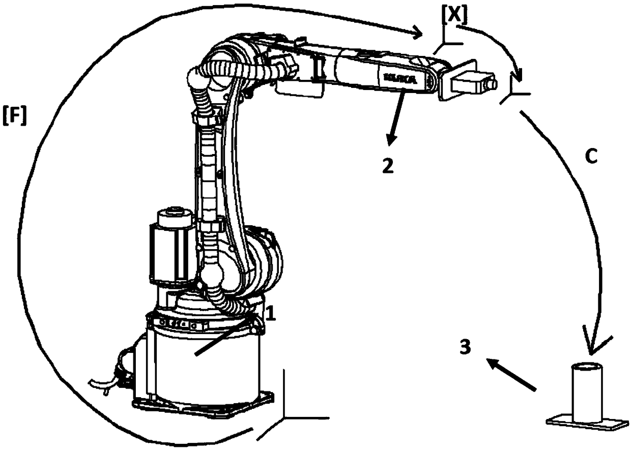
[0019] refer to figure 1 , The hand-eye calibration system based on 3D vision provided by the present invention is composed of a KUKA manipulator 1, a 3D vision sensor 2 and a measuring part 3. The 3D vision sensor is installed on the flange of KUKA manipulator 1, and the measuring part 3 is placed on the ground and keeps its position unchanged.

[0020] First, install the 3D vision sensor at the end of the KUKA manipulator, and connect it to the computer through a network cable. Enter the IP address in the IE browser to displ...


PUM


Abstract

The invention discloses a hand and eye calibration method based on 3D vision. The method comprises the following steps of: installing a 3D visual sensor at the tail end of a manipulator; placing a measuring workpiece on the ground; calculating a homogeneous transformation matrix of a manipulator tail end flange coordinate system relative to a robot based coordinate system; moving a robot to different positions, and reading different three-dimensional positions (X, Y, Z) of the circle center of a circular hole of the measuring workpiece in a ceramic coordinate system by virtue of the 3D visualsensor; and solving the homogeneous transformation matrix between the manipulator flange coordinate system and the 3D visual sensor coordinate system by adopting a least square method based on the system of simultaneous equations. The method disclosed by the invention acquires the homogeneous transformation matrix between manipulator flange coordinates and the 3D visual sensor coordinates by calculation and by reading the internal variable values of the robot and the 3D visual sensor, is simple and high in accuracy value and can provide conversion basis for three-dimensional point cloud precise reconstruction of a large-size component.

Description

technical field [0001] The invention relates to the field of 3D vision, in particular to a hand-eye calibration method based on 3D vision. Background technique [0002] In the process of precise inspection of large engineering parts, 3D vision sensors are required to collect 3D point cloud data of parts and compare them with point cloud data of standard parts. The 3D vision sensor has a limited shooting area. Large parts are usually collected in segments and reconstructed through data registration methods. Although the target can be achieved, the accuracy is relatively low. Another way to reconstruct large parts is to put the segmented 3D point cloud data acquired by the 3D vision sensor into the same actual coordinate system and perform 3D reconstruction. This method can reduce the cost of 3D point cloud data reconstruction. The precision error caused by the algorithm. Contents of the invention [0003] The technical problem to be solved by the present invention is to p...

Claims


Application Information

Patent Timeline
Patent Type & Authority Applications(China)
IPC IPC(8): B25J9/16
CPCB25J9/1607B25J9/1692
Inventor 宫正葛继谷森汝长海孙钰
Owner JIANGSU JICUI MICRO NANO AUTOMATION SYST & EQUIP TECH RES INST CO LTD
Why Eureka
Try Eureka