
A reference signal transmission method, device, base station and terminal

A transmission method and reference signal technology, applied in the field of communication applications, can solve problems such as no solution

Active Publication Date: 2020-12-04
DATANG MOBILE COMM EQUIP CO LTD
View PDF1 Cites 0 Cited by
  • Summary
  • Abstract
  • Description
  • Claims
  • Application Information

AI Technical Summary

Problems solved by technology

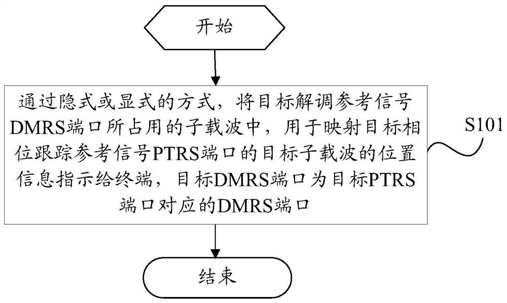
[0005] The purpose of the present invention is to provide a reference signal transmission method, device, base station and terminal to solve the problem of how to map the PTRS port to the subcarrier where the DMRS port corresponding to the port is located, and there is currently no corresponding solution.

Method used


Image

  • A reference signal transmission method, device, base station and terminal
  • A reference signal transmission method, device, base station and terminal
  • A reference signal transmission method, device, base station and terminal

Examples


Embodiment 1

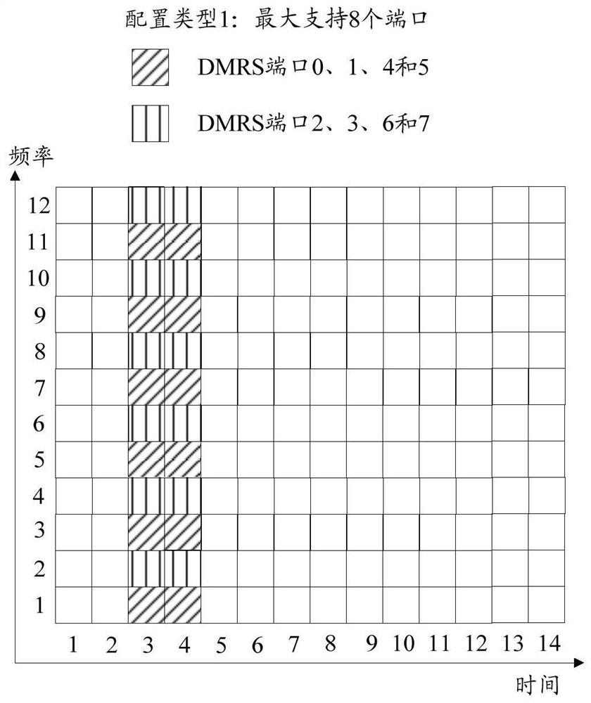
[0163] Suppose the configuration type of DMRS is Figure 2b configuration type in .

[0164] base station:

[0165] (1) The system predefines the S=1th subcarrier occupied by each DMRS port in a PRB as a preset reference subcarrier. The preset reference subcarrier is known to both the base station and the terminal. That is, for DMRS ports 0, 1, 4 and 5, the preset reference subcarrier is subcarrier 1, and for DMRS ports 2, 3, 6 and 7, the preset reference subcarrier is subcarrier 2.

[0166] (2) The base station is equipped with 2 PTRS ports. The base station determines that PTRS port 0 has a group correspondence with DMRS ports 0-3, which uses the precoding of DMRS port 0, ie it has a port correspondence with DMRS port 0. The base station determines that PTRS port 1 has a group correspondence with DMRS ports 4-7, which uses the precoding of DMRS port 4, ie it has a port correspondence with DMRS port 4. It is assumed that the value of S_offset represents the number of off...

Embodiment 2

[0174] It is assumed that the above position information is the offset information between the subcarriers used to map the PTRS ports and the preset reference subcarriers corresponding to the DMRS ports among the subcarriers occupied by each DMRS port in the preset DMRS port group.

[0175] base station:

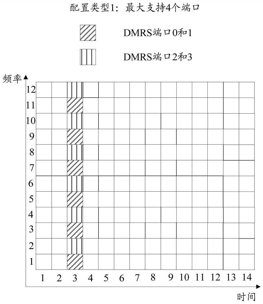
[0176] (1) Figure 2a Among them, it is divided into 2 DMRS port groups based on the carrier position. Among them, ports 0 and 1 are a group, and ports 2 and 3 are a group; Figure 2b Among them, it is divided into two DMRS port groups based on the carrier position, where ports 0, 1, 4 and 5 are a group, and ports 2, 3, 6 and 7 are a group; Figure 2c Among them, it is divided into three DMRS port groups based on the carrier position, where ports 0 and 1 are a group, ports 2 and 3 are a group, and ports 4 and 5 are a group; Figure 2d Among them, it is divided into 3 DMRS port groups based on carrier position, among which ports 0, 1, 6 and 7 are a group, ports 2, 3, 8 and...


PUM


Abstract

The present invention provides a reference signal transmission method, device, base station and terminal, and solves the problem of how to map a PTRS port to the subcarrier where the DMRS port corresponding to the port is located, and there is no corresponding solution at present. The transmission method of the present invention includes: in an implicit or explicit manner, indicating to In the terminal, the target DMRS port is a DMRS port corresponding to the target PTRS port. The invention realizes the purpose of performing PTRS transmission according to the location information, and can avoid mapping of different PTRS ports to the same sub-carrier, effectively ensuring the orthogonality between different PTRS ports.

Description

technical field [0001] The present invention relates to the technical field of communication applications, in particular to a reference signal transmission method, device, base station and terminal. Background technique [0002] Phase noise comes from the local oscillators in the transmitter and receiver, which will have an impact on the transmission of multi-carrier signals, especially in the high frequency band (above 6GHz), the impact of phase noise will be more serious, and it is necessary to perform phase noise on the received signal compensation to ensure system performance. By introducing a phase tracking reference signal (PTRS) at the transmitting end, the phase change caused by phase noise can be tracked, so that the receiving end can estimate the phase noise of the link and compensate for the influence of the phase noise. [0003] In the new air interface NR system, PTRS is transmitted in the frequency band scheduled by the user. According to the frequency domain ...

Claims


Application Information

Patent Timeline
Patent Type & Authority Patents(China)
IPC IPC(8): H04L5/00
CPCH04L5/0048H04L5/0094H04L5/0051H04L5/0023H04W56/0035
Inventor 李辉高秋彬塔玛拉卡·拉盖施陈润华苏昕缪德山黄秋萍
Owner DATANG MOBILE COMM EQUIP CO LTD
Learn More