
A welding conveying production line based on connection transportation

A production line and mounting rack technology, applied in storage devices, metal processing equipment, feeding devices, etc., can solve problems such as high cost and low production efficiency

Active Publication Date: 2020-02-11
NANTONG INST OF TECH
View PDF9 Cites 0 Cited by
  • Summary
  • Abstract
  • Description
  • Claims
  • Application Information

AI Technical Summary

Problems solved by technology

[0002] At present, some pipelines use the coiling machine to coil the steel plate into shape and then weld it. Before the steel plate enters the coiling machine, it is generally transported through the conveying production line, but the existing output production line still transports the steel plate to the coiling machine. It needs to be hoisted by other devices, resulting in low production efficiency and high cost, so a welding conveyor production line based on connection transportation is needed

Method used


Image

  • A welding conveying production line based on connection transportation
  • A welding conveying production line based on connection transportation
  • A welding conveying production line based on connection transportation

Examples


Embodiment

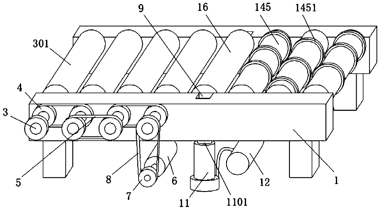
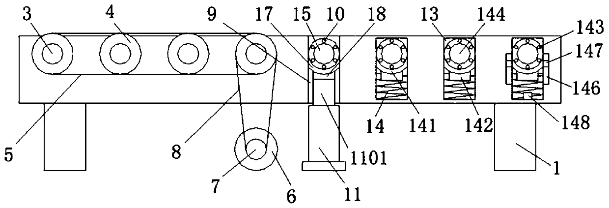
[0029] The following is attached Figure 1-7 The present invention is described in further detail.

[0030] A welding conveying line based on connection transportation, such as Figure 1-2 As shown, including the mounting frame 1, the surface of the mounting frame 1 is fixedly installed with a fixed bearing 2, a plurality of fixed bearings 2 are evenly distributed on the surface of the mounting frame 1, the inner ring of the fixed bearing 2 is fixedly connected with a power shaft 3, and the power shaft 3 The surface of the power shaft 3 is fixedly connected with a power roller 301, one end of the power shaft 3 runs through and extends to the surface of the installation frame 1, and one end of the power shaft 3 is fixedly connected with a pulley group 4, and a plurality of pulley groups 4 are connected through transmission belts 5. There is a power motor 6 under the frame 1. The model of the power motor 6 includes YE2-80M1-2. The output shaft of the power motor 6 is fixedly co...

Embodiment 1

[0036] A welding conveying line based on connection transportation, such as Figure 1-2 As shown, including the mounting frame 1, the surface of the mounting frame 1 is fixedly installed with a fixed bearing 2, a plurality of fixed bearings 2 are evenly distributed on the surface of the mounting frame 1, the inner ring of the fixed bearing 2 is fixedly connected with a power shaft 3, and the power shaft 3 The surface of the power shaft 3 is fixedly connected with a power roller 301, one end of the power shaft 3 runs through and extends to the surface of the installation frame 1, and one end of the power shaft 3 is fixedly connected with a pulley group 4, and a plurality of pulley groups 4 are connected through transmission belts 5. There is a power motor 6 under the frame 1. The model of the power motor 6 includes YE2-80M1-2. The output shaft of the power motor 6 is fixedly connected with the driving wheel 7 through a coupling, and the driving wheel 7 is connected to one of the...

Embodiment 2

[0042] A welding conveying line based on connection transportation, such as Figure 1-2As shown, including the mounting frame 1, the surface of the mounting frame 1 is fixedly installed with a fixed bearing 2, a plurality of fixed bearings 2 are evenly distributed on the surface of the mounting frame 1, the inner ring of the fixed bearing 2 is fixedly connected with a power shaft 3, and the power shaft 3 The surface of the power shaft 3 is fixedly connected with a power roller 301, one end of the power shaft 3 runs through and extends to the surface of the installation frame 1, and one end of the power shaft 3 is fixedly connected with a pulley group 4, and a plurality of pulley groups 4 are connected through transmission belts 5. There is a power motor 6 under the frame 1. The model of the power motor 6 includes YE2-80M1-2. The output shaft of the power motor 6 is fixedly connected with the driving wheel 7 through a coupling, and the driving wheel 7 is connected to one of the ...


PUM


Abstract

The invention discloses a welding conveying production line based on connecting transportation. The production line comprises a mounting frame; fixed bearings are fixedly mounted on the surface of themounting frame; multiple fixed bearings are uniformly distributed on the surface of the mounting frame; inner rings of the fixed bearings are fixedly connected with power shafts; the surfaces of thepower shafts are fixedly connected with power rollers; one ends of the power shafts penetrate through and extend to the surface of the mounting frame; the other ends of the power shafts are fixedly connected with belt wheel sets; and multiple belt wheel sets are in transmission connection through transmission belts. In the welding conveying production line based on connecting transportation, multiple buffer adhesive tapes are fixedly connected to the surface of an auxiliary roller, and are uniformly distributed on the surface of the auxiliary roller; in the actual use process, the buffer adhesive tapes are contacted with the surface of a steel plate; one end of the steel plate is ejected on a bearing roller; and when the steel plate is aslant fed in a plate rolling machine, the buffer adhesive tapes achieve the effect of increasing the friction force of the steel plate to prevent damage of the plate rolling machine caused by higher speed of sliding of the steel plate in the plate rolling machine.

Description

technical field [0001] The present invention relates to the technical field of conveying production line, more specifically, it relates to a welding conveying production line based on connection transportation. Background technique [0002] At present, some pipelines use the coiling machine to coil the steel plate into shape and then weld it. Before the steel plate enters the coiling machine, it is generally transported through the conveying production line, but the existing output production line still transports the steel plate to the coiling machine. It needs to be hoisted by other devices, resulting in low production efficiency and high cost, so a welding conveyor production line based on connection transportation is needed. Contents of the invention [0003] In view of the deficiencies in the prior art, the purpose of the present invention is to provide a welding conveying production line based on connection transportation, which has the characteristics of automatical...

Claims


Application Information

Patent Timeline
Patent Type & Authority Patents(China)
IPC IPC(8): B21D43/08
CPCB21D43/08
Inventor 林盛昌孙翱耿苏桐陈浩孟子豪郭一鸣董秋伟
Owner NANTONG INST OF TECH
Learn More