Capacitor welding and clamping apparatus and welding signal processing method

A signal processing and welding device technology, applied in capacitors, auxiliary devices, welding equipment, etc., can solve problems such as high cost, welding needle system interference, inaccurate control, etc., to reduce labor costs, reduce manual operations, and improve work efficiency. Effect

Inactive Publication Date: 2018-08-24
安徽亦知电气设备有限公司
View PDF0 Cites 0 Cited by
  • Summary
  • Abstract
  • Description
  • Claims
  • Application Information

AI Technical Summary

Problems solved by technology

[0003] The existing welding device is inaccurate in grasping the welding position during welding, there are few side welding devices, and the efficiency is low, the cost is high, the operation steps are complicated, and it is inconvenient to use
[0004] In the process of welding capacitors, there will be a lot of interference from the external environment, resulting in noise interference to the welding needle system, inaccurate judgment of the welding position, and inaccurate welding positions of the capacitors, resulting in poor welding quality between the capacitors.

Method used


Image

  • Capacitor welding and clamping apparatus and welding signal processing method
  • Capacitor welding and clamping apparatus and welding signal processing method
  • Capacitor welding and clamping apparatus and welding signal processing method

Examples


Embodiment Construction

[0040] The present invention will be further described in detail below in conjunction with the accompanying drawings, so that those skilled in the art can implement it with reference to the description.

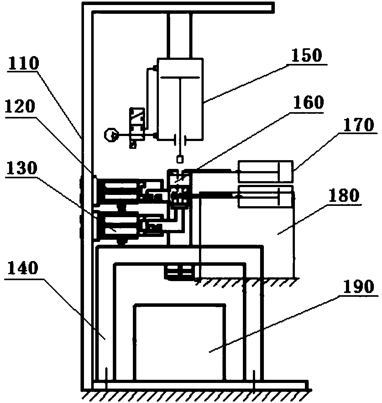
[0041] Such as figure 1 As shown, the present invention provides a capacitor welding clamping device, including: a load-bearing frame 110, a push-down mechanism 150, a welding device 120, a clamping device 130, a support shell 140, a receiving box 190, a set-up mold 160, Capacitor monomer feeding device 170 and assembly feeding device 180 .

[0042] The load-bearing frame 110 includes an upper horizontal plate, vertically connected columns and a lower horizontal plate; the load-bearing frame 110 is a cuboid structure with an opening on one side; the push-down mechanism 150 is arranged inside the load-bearing frame, and one end is connected to the upper horizontal plate The bottom of the push-down mechanism 150 is provided with a push-down block, which is driven by the push-d...


PUM


Abstract

The invention discloses a welding signal processing method of a capacitor welding clamping apparatus; the capacitor welding clamping apparatus comprises a bearing framework, a downward pushing mechanism, a supporting shell and a combined mould, wherein the bearing framework adopts a cuboid structure with an opening in one side; a welding apparatus and a clamping apparatus are fixedly connected with the middle part of a stand column from top to bottom in sequence; one end of the downward pushing mechanism is connected with the lower part of an upper transverse plate; the interior of the supporting shell adopts a hollow structure, and the supporting shell is arranged at the bottom of the bearing framework and perpendicularly connected with a lower transverse plate; the combined mould is connected with the supporting shell and adopts a cuboid structure; a capacitor feeding port is formed in the top end of one side of the combined mould, and a combined body feeding port is formed below, wherein the downward pushing mechanism and the supporting shell and the combined mould are coaxial; and the downward pushing mechanism can push a capacitor arranged in the capacitor feeding port to thecombined body to enable the two parts to be connected, and to perform side surface welding through the welding mechanism. By virtue of the welding signal processing method of the capacitor welding clamping apparatus, the shortcoming that the existing equipment cannot perform side surface welding is overcome, manual operation is reduced, and working efficiency is improved.

Description

technical field [0001] The invention relates to a capacitance welding clamping device, which belongs to the field of capacitance welding. Background technique [0002] At present, the side welding of capacitors is often done manually. Only the side welding of capacitors requires at least two people to complete. One person prepares the materials and the other completes the welding. A maximum of two shifts per day, a total of 16 hours of work, the number of completed capacitor side welding is about 1600, the welding quality is uneven, and labor costs have become a big expense. For this reason, we designed the capacitor automatic side welding assembly machine, which can complete all automatic equipment on the basis of ensuring the welding quality, and its workmanship is fine. One person can control 5-10 sets of this equipment, which greatly improves the work efficiency. Using this equipment, it can work 24 hours a day, and the output of one machine is about 3000 pieces, and th...

Claims


Application Information

Patent Timeline
IPC IPC(8): H01G13/00B23K37/04B23K37/00
CPCH01G13/00B23K37/00B23K37/04B23K37/0443
Inventor 徐从业章伟
Owner 安徽亦知电气设备有限公司
Why Eureka
Try Eureka