Machine oil filler cap machining equipment

A technology for oil filler caps and processing equipment, applied in metal processing equipment, welding equipment, auxiliary welding equipment, etc., can solve the problems of reduced production efficiency, long time, troublesome operation, etc., to achieve improved efficiency, simple operation, and guaranteed processing Effect

Inactive Publication Date: 2022-07-12
临海市中等职业技术学校(临海市技工学校)
View PDF1 Cites 0 Cited by
  • Summary
  • Abstract
  • Description
  • Claims
  • Application Information

AI Technical Summary

Problems solved by technology

[0004] However, the processing of the fuel filler cap has the following problems: the production of the fuel filler cap is manually completed, the operation is cumbersome, the time is long, the production efficiency is reduced, and it is not suitable for mass production

Method used


Image

  • Machine oil filler cap machining equipment
  • Machine oil filler cap machining equipment
  • Machine oil filler cap machining equipment

Examples


Embodiment 1

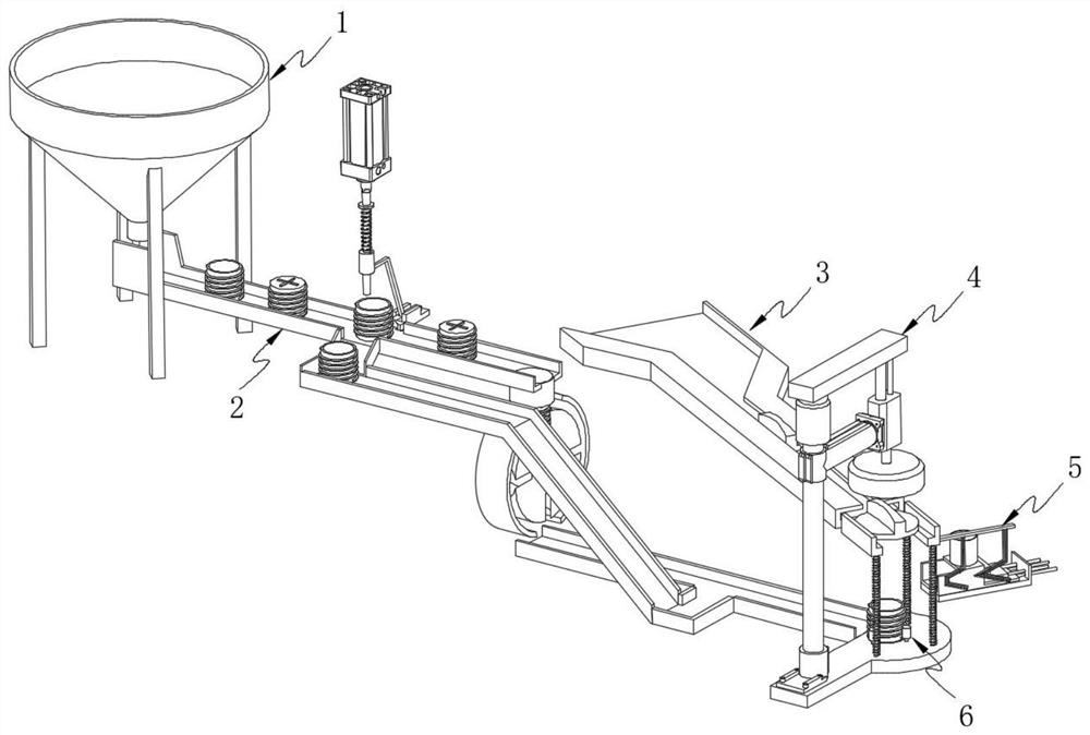
[0047] like figure 1 As shown, the present invention provides a fuel filler cap processing equipment, comprising: a vibrating funnel 1;

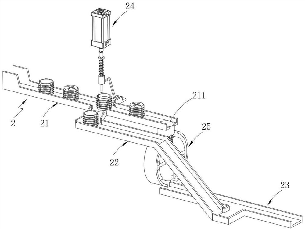
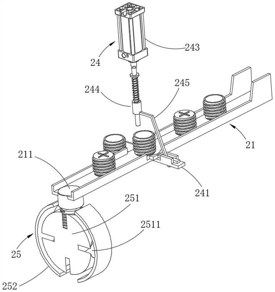
[0048] The first transmission part 2, the first transmission part 2 is arranged on one side of the vibration funnel 1 to transmit the lower casing;

[0049] The second transmission part 3, the second transmission part 3 is arranged on one side of the first transmission part 2 to transmit the upper casing;

[0050] The spin welding processing part 4, the spin welding processing part 4 is arranged at the output end of the first transmission part 2 to assemble the lower casing and the upper casing together by a rotating welding process;

[0051] Pushing member 5, the pushing member 5 is arranged on one side of the second transmission member 3 to push the sponge ball into the lower casing.

[0052] In the present invention, the lower casing is put into the vibrating funnel 1, the first transmission part 2 transmits the lower casing, the secon...

Embodiment 2

[0087] like Figure 10 As shown, the same or corresponding components as those in the first embodiment are given the corresponding reference numerals as in the first embodiment. For the sake of brevity, only the points of difference from the first embodiment are described below. The difference between the second embodiment and the first embodiment is:

[0088] This embodiment also includes a positioning member 6, which is arranged on the spin welding processing member 4 to position the lower casing.

[0089] further, as Figure 10 and Figure 11 As shown, the positioning member 6 includes: a cross groove 421, which is opened on the worktable 42; a transmission shaft 61, a plurality of sets of transmission shafts 61 are arranged beside the cross groove 421 to rotate the lower casing; a connecting rod 62, a connecting rod 62 is installed at the bottom of the transmission shaft 61; gear a63, gear a63 is installed at the bottom of the connecting rod 62; drive assembly 64, one e...


PUM


Abstract

The invention provides machine oil filler cap machining equipment. The machine oil filler cap machining equipment comprises a vibration funnel; the first conveying part is arranged on one side of the vibration funnel and is used for conveying the lower shell; the second transmission part is arranged on one side of the first transmission part and is used for transmitting the upper shell; and the rotary welding machining part is arranged at the output end of the first conveying part and used for assembling the lower shell and the upper shell together through a rotary welding process. A lower shell is conveyed through the first conveying component, an upper shell is conveyed through the second conveying component, a sponge ball is pushed into the lower shell through the pushing component, the lower shell and the upper shell are assembled together through the rotary welding process through the rotary welding processing component, assembly of the engine oil filler cap is completed, operation is simple, and the efficiency is high. The production efficiency is greatly improved, and the method is suitable for mass production.

Description

technical field [0001] The invention relates to the technical field of processing equipment, in particular to a processing equipment for oil filler caps. Background technique [0002] The oil filler cap is one of the basic parts of the engine. When the engine is filled with oil, the oil filler cap needs to be opened. At other times, the oil filler cap is sealed. The conventional method is to set a tubular shape on the cylinder head cover on the engine. The filling port is usually sealed with a cap. When filling oil, unscrew the oil filling port cap and add oil through the filling port. [0003] Chinese Patent Application No. 201520254637.3 discloses a new type of oil filler cap, the structure of which is as follows Figure 13 As shown, it includes an upper casing 71, a lower casing 72 and a sponge ball 73, the upper casing 71 and the lower casing 72 are plastic parts, and the sponge ball 73 absorbs the liquefied oil and gas. The processing procedure is as follows: manually ...

Claims


Application Information

Patent Timeline
Patent Type & Authority Applications(China)
IPC IPC(8): B23K37/00B07B13/00B07B13/16
CPCB23K37/00B07B13/00B07B13/16
Inventor 金超焕陈兆强朱根升陈慧韩勇娜单才华徐高杨
Owner 临海市中等职业技术学校(临海市技工学校)
Why Eureka
Try Eureka