Plate snapping machine and aerated concrete blank manufacturing device

A technology of trigger and body, which is applied in the field of aerated concrete body manufacturing equipment, and can solve the problems of high difficulty in overhaul and maintenance, and low breaking efficiency

Active Publication Date: 2019-03-19
HUNAN SANY KUAIERJU RESIDENTIAL IND CO LTD
View PDF7 Cites 7 Cited by
  • Summary
  • Abstract
  • Description
  • Claims
  • Application Information

AI Technical Summary

Problems solved by technology

[0005] The purpose of the present invention is to provide a board breaker to solve the technical problems of the prior art that the board breaker has low breaking efficiency and high cost, overhaul and maintenance difficulty

Method used


Image

  • Plate snapping machine and aerated concrete blank manufacturing device
  • Plate snapping machine and aerated concrete blank manufacturing device
  • Plate snapping machine and aerated concrete blank manufacturing device

Examples


Embodiment 1

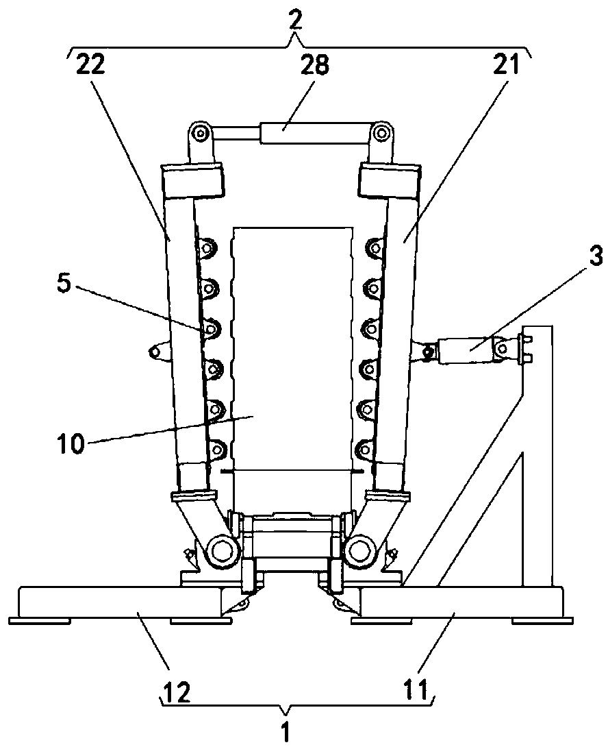
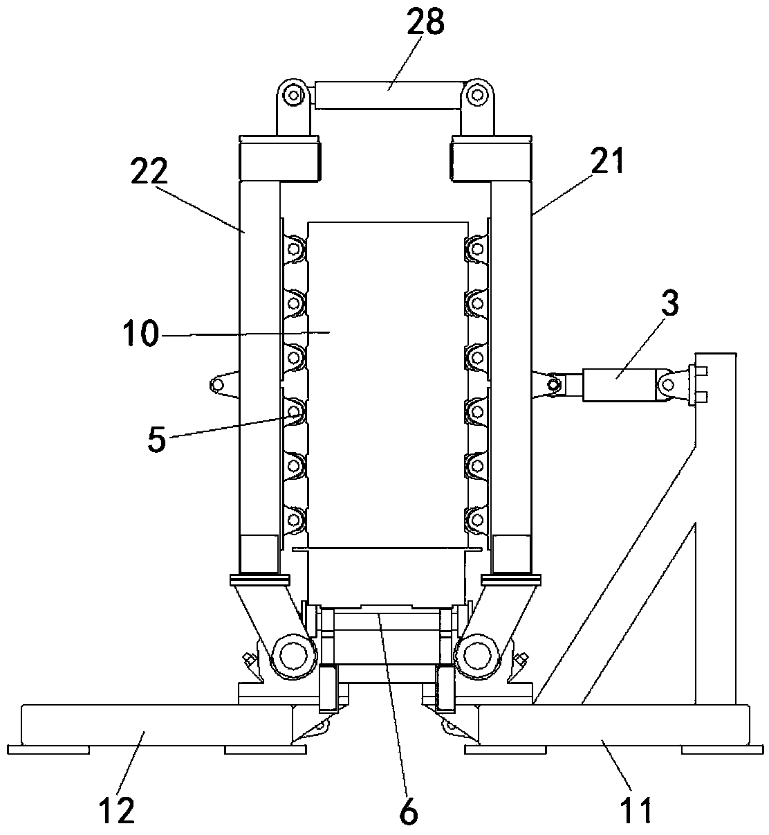
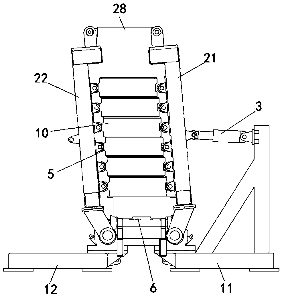
[0050] The board breaking machine provided in this embodiment, such as Figure 1 to Figure 11 As shown, it includes a breaking assembly 2, a driving assembly 3 and an installation structure 1; Components 22 are respectively movably connected with installation structure 1; drive assembly 3 is connected with split component 2, and is used to drive the first split component 21 and the second split component 22 to tilt in the same direction, so that the first split component 21 and the second split component The two breaking parts 22 cooperate to split a plurality of blanks 10 along the direction of the cutting surface of the blanks.

[0051] Wherein, the first breaking part 21 and the second breaking part 22 are rotationally connected with the installation structure 1 respectively, or the first breaking part 21 and the second breaking part 22 are respectively slidingly connected with the installation structure 1 . The installation structure 1 may be a base, or any suitable form ...

Embodiment 2

[0101] The device for manufacturing an aerated concrete body provided in this embodiment includes the board breaking machine provided in Embodiment 1. The first breaking part 21 and the second breaking part 22 are respectively arranged on both sides of a plurality of green bodies 10, and after the expansion and contraction drives the first breaking part 21 and the second breaking part 22 to tilt in the same direction, the first breaking part Part 21 presses one side of a plurality of green bodies 10, and the second splitting member 22 blocks the other side of a plurality of green bodies 10, so that adjacent green bodies 10 are staggered by a suitable distance in the horizontal direction, thereby breaking apart the stuck ones. Body 10. The aerated concrete body manufacturing device provided in this embodiment can separate a plurality of coherent green bodies 10 in one operation to improve the splitting efficiency, and a small amount of oil cylinders are required in the drive as...


PUM


Abstract

The invention provides a plate snapping machine and an aerated concrete blank manufacturing device and relates to the technical field of aerated concrete blank manufacturing equipment. The plate snapping machine comprises a plate snapping assembly, a driving assembly and an installation structure. The plate snapping assembly comprises a first plate snapping piece and a second plate snapping piecewhich are oppositely arranged, and the first plate snapping piece and the second plate snapping piece are movably connected with the installation structure. The driving assembly is connected with theplate snapping assembly and is used for driving the first plate snapping piece and the second plate snapping piece to tilt in the same direction, so that the first plate snapping piece and the secondplate snapping piece are matched to snap a plurality of blanks in the direction of the blank cutting surface. According to the plate snapping machine, a plurality of adhered blanks can be snapped apart by one-time operation, so that the snapping efficiency is improved; and a small amount of oil cylinders are required in the driving assembly, so that the structural complexity and cost of the platesnapping machine can be reduced, and the difficulty in maintenance and repair can be reduced.

Description

technical field [0001] The invention relates to the technical field of production equipment for aerated concrete blanks, in particular to a board breaking machine and an aerated concrete blank manufacturing device with the board breaking machine. Background technique [0002] After the aerated concrete body is cut into several standard width plates or blocks by the cutting unit, it is put into the autoclave for high temperature and high pressure steam curing. After the steam curing is completed, the adjacent green bodies will stick together and bonded The force is relatively large, and it is necessary to use special breaking board equipment for breaking. [0003] The current board breaking machine includes a breaking mechanism and a fixed frame. The breaking mechanism is composed of two frames. Two rows of horizontal clamping oil cylinders are respectively fixed on both sides of each frame to clamp the green body. Multiple tops are arranged between the frames. Lift the oil ...

Claims


Application Information

Patent Timeline
Patent Type & Authority Applications(China)
IPC IPC(8): B28B11/14
CPCB28B11/14
Inventor 易达幸贾海云黄勃
Owner HUNAN SANY KUAIERJU RESIDENTIAL IND CO LTD
Why Eureka
Try Eureka