Clearing machine for accumulated snow on garden road

A cleaning machine and road technology, applied in the field of cleaning machines, can solve the problems of low labor intensity, high labor intensity, long roads, etc., and achieve the effect of avoiding hand soreness and high work efficiency.

Inactive Publication Date: 2019-03-19
吴开英
View PDF7 Cites 4 Cited by
  • Summary
  • Abstract
  • Description
  • Claims
  • Application Information

AI Technical Summary

Problems solved by technology

[0003] In order to overcome the shortcomings that people need to constantly swing the shovel to clear the snow, the hands are easy to be sore and affect the follow-up work efficiency, and the road is relatively long, it takes a lot of time to clear it, and the labor intensity is high. Therefore, the technical problem of the present invention is : Provide a snow clearing machine for garden roads that can clear snow more quickly, has high work efficiency, is short in time consumption, and has low labor intensity

Method used


Image

  • Clearing machine for accumulated snow on garden road
  • Clearing machine for accumulated snow on garden road
  • Clearing machine for accumulated snow on garden road

Examples


Embodiment 1

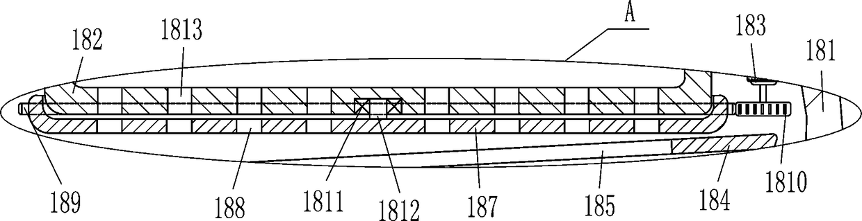
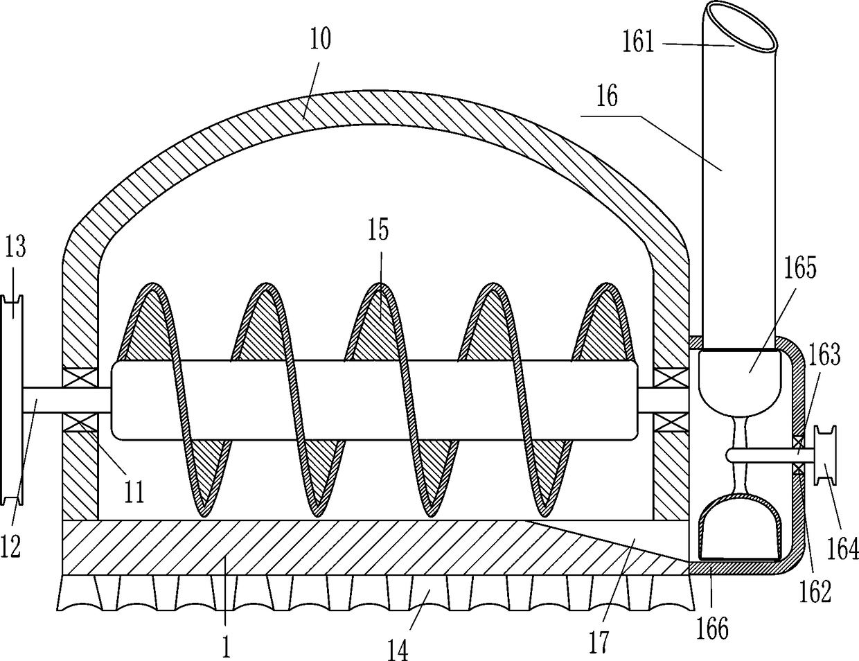
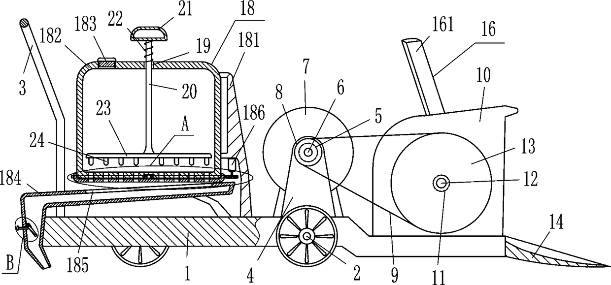
[0023] A garden road snow removal machine, such as Figure 1-5As shown, it includes base plate 1, wheel 2, push handle 3, support plate 4, first bearing seat 5, first rotating shaft 6, biaxial motor 7, first pulley 8, first flat belt 9, housing 10, the first Two bearing blocks 11, a second rotating shaft 12, a second pulley 13, a shovel plate 14, a screw conveying shaft 15 and a snow removal device 16, the front and rear sides of the middle part of the base plate 1 and the left front and back sides of the bottom plate 1 are rotatably connected with wheels 2, The pusher 3 is installed on the left side of the top of the base plate 1, and the right side of the base plate 1 is equipped with a shovel plate 14 that can move the snow shovel. The upper part is embedded with a first bearing seat 5, and the bearings in the first bearing seat 5 are connected to the first rotating shaft 6 in an interference fit. The double-axis motor 7 is installed in the middle of the top of the bottom p...

Embodiment 2

[0025] A garden road snow removal machine, such as Figure 1-5 As shown, it includes base plate 1, wheel 2, push handle 3, support plate 4, first bearing seat 5, first rotating shaft 6, biaxial motor 7, first pulley 8, first flat belt 9, housing 10, the first Two bearing blocks 11, a second rotating shaft 12, a second pulley 13, a shovel plate 14, a screw conveying shaft 15 and a snow removal device 16, the front and rear sides of the middle part of the base plate 1 and the left front and back sides of the bottom plate 1 are rotatably connected with wheels 2, The pusher 3 is installed on the left side of the top of the base plate 1, and the right side of the base plate 1 is equipped with a shovel plate 14 that can move the snow shovel. The upper part is embedded with a first bearing seat 5, and the bearings in the first bearing seat 5 are connected to the first rotating shaft 6 in an interference fit. The double-axis motor 7 is installed in the middle of the top of the bottom ...

Embodiment 3

[0028] A garden road snow removal machine, such as Figure 1-5 As shown, it includes base plate 1, wheel 2, push handle 3, support plate 4, first bearing seat 5, first rotating shaft 6, biaxial motor 7, first pulley 8, first flat belt 9, housing 10, the first Two bearing blocks 11, a second rotating shaft 12, a second pulley 13, a shovel plate 14, a screw conveying shaft 15 and a snow removal device 16, the front and rear sides of the middle part of the base plate 1 and the left front and back sides of the bottom plate 1 are rotatably connected with wheels 2, The pusher 3 is installed on the left side of the top of the base plate 1, and the right side of the base plate 1 is equipped with a shovel plate 14 that can move the snow shovel. The upper part is embedded with a first bearing seat 5, and the bearings in the first bearing seat 5 are connected to the first rotating shaft 6 in an interference fit. The double-axis motor 7 is installed in the middle of the top of the bottom ...


PUM


Abstract

The invention relates to a clearing machine, in particular to a clearing machine for accumulated snow on a garden road. The technical problems are solved by the clearing machine for accumulated snow on the garden road, wherein the clearing machine can clear off the accumulated snow more rapidly, and is high in working efficiency, short in consumed time and low in labor intensity. In the technicalimplementation scheme, the clearing machine for the accumulated snow on the garden road comprises a bottom plate, wheels, a pushing hand, a supporting plate, a first bearing pedestal, a first rotatingshaft, a double-shaft motor, a first belt wheel, a first flat belt and others; the wheels are rotatably connected to the front and back sides of the middle and the front and back sides of the left ofthe bottom plate respectively, and the pushing hand is installed on the left side of the top of the bottom plate. By pushing the machine, a shoveling plate can shovel up the snow, then the shoveled snow is discharged to the two sides of the road through a snow discharging device, it is not needed to manually shovel the snow to the sides of the road, hands are prevented from being ached, working efficiency is high, salt is scattered onto the road through a salt scattering device after the snow is shoveled, and therefore the snow which falls onto the road is melt more rapidly and not easily accumulated.

Description

technical field [0001] The invention relates to a clearing machine, in particular to a snow clearing machine for garden roads. Background technique [0002] After snowing in winter, there will be a lot of snow on the garden roads. A lot of snow will easily lead to dangerous accidents caused by vehicle skidding, and it is also easy to cause pedestrians to fall and be injured. The snow needs to be removed. Usually people use shovels To clear the snow, because people need to constantly swing the shovel to clear the snow to the side of the road, the hands will be sore after a long time, which will affect the follow-up work efficiency, and the road is large and long, it takes a lot of time to clear it, and the labor intensity is high. , so many people are required to clear the snow on the road at the same time, so the labor cost is high. Contents of the invention [0003] In order to overcome the shortcomings that people need to constantly swing the shovel to clear the snow, t...

Claims


Application Information

Patent Timeline
Patent Type & Authority Applications(China)
IPC IPC(8): E01H5/07E01H10/00
CPCE01H5/07E01H10/007
Inventor 吴开英
Owner 吴开英
Why Eureka
Try Eureka