Efficient grinding equipment for brake clutch plate production

A clutch, high-efficiency technology, used in grinding/polishing equipment, grinding devices, grinding machine tools, etc., can solve problems such as low labor intensity, high labor intensity, and injuries

Active Publication Date: 2017-07-18
东营宝丰汽车配件有限公司
View PDF8 Cites 3 Cited by
  • Summary
  • Abstract
  • Description
  • Claims
  • Application Information

AI Technical Summary

Problems solved by technology

[0005] In order to overcome the shortcomings of manual grinding of the brake clutch plate, the labor intensity is high, the work efficiency is low, it is easy to be injured during grinding, and dust will appear during the grinding process, which will affect the surrounding environment. The technical problem to be solved by the invention It is to provide a high-efficiency grinding equipment for the production of brake clutch plates with low labor intensity and low work efficiency, which is not easy to be injured during grinding and does not affect the surrounding environment.

Method used


Image

  • Efficient grinding equipment for brake clutch plate production
  • Efficient grinding equipment for brake clutch plate production
  • Efficient grinding equipment for brake clutch plate production

Examples


Embodiment 1

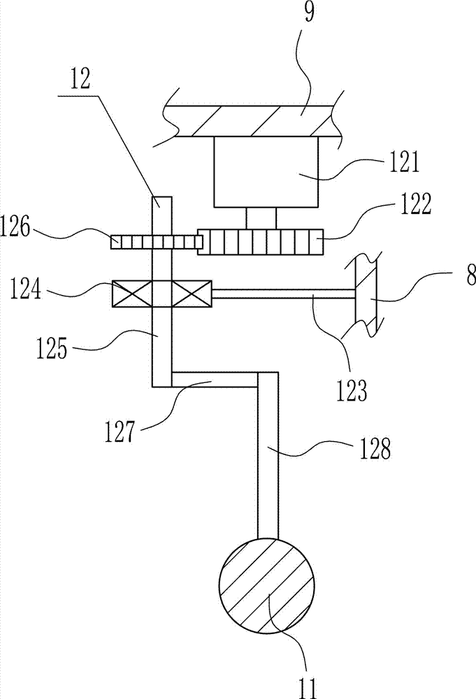
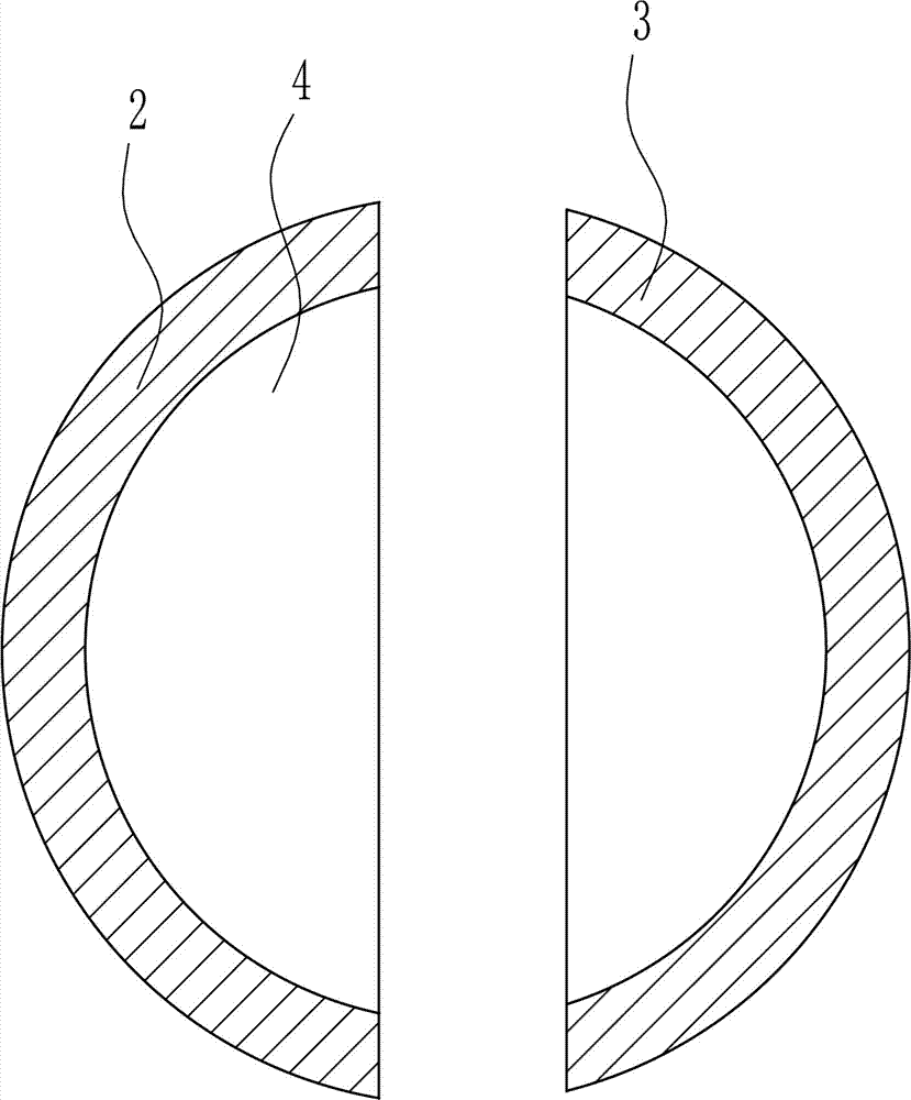
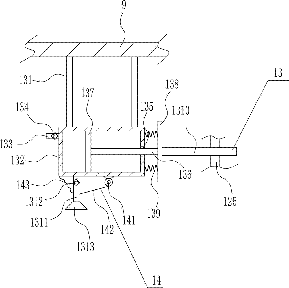
[0040] A high-efficiency grinding equipment for the production of brake clutch plates, such as Figure 1-11 As shown, it includes base 1, first placement plate 2, second placement plate 3, right side plate 5, first slide rail 6, first slider 7, mounting plate 8, horizontal plate 9, grinding ball 10, upper and lower The mobile device 11 and the rotating device 12, the left side of the top of the base 1 is installed with a first placement plate 2 through bolt connection, the right side of the top of the base 1 is equipped with a second placement plate 3 through a bolt connection, the first placement plate 2 and The top of the second placement plate 3 has placement grooves 4, the placement grooves 4 are symmetrically arranged, and the right side of the top of the base 1 is equipped with a right side plate 5 by means of bolt connection, and the right side plate 5 is positioned at the right side of the second placement plate 3, The first slide rail 6 is installed on the top of the ...

Embodiment 2

[0042] A high-efficiency grinding equipment for the production of brake clutch plates, such as Figure 1-11 As shown, it includes base 1, first placement plate 2, second placement plate 3, right side plate 5, first slide rail 6, first slider 7, mounting plate 8, horizontal plate 9, grinding ball 10, upper and lower The mobile device 11 and the rotating device 12, the left side of the top of the base 1 is installed with a first placement plate 2 through bolt connection, the right side of the top of the base 1 is equipped with a second placement plate 3 through a bolt connection, the first placement plate 2 and The top of the second placement plate 3 has placement grooves 4, the placement grooves 4 are symmetrically arranged, and the right side of the top of the base 1 is equipped with a right side plate 5 by means of bolt connection, and the right side plate 5 is positioned at the right side of the second placement plate 3, The first slide rail 6 is installed on the top of the ...

Embodiment 3

[0045] A high-efficiency grinding equipment for the production of brake clutch plates, such as Figure 1-11 As shown, it includes base 1, first placement plate 2, second placement plate 3, right side plate 5, first slide rail 6, first slider 7, mounting plate 8, horizontal plate 9, grinding ball 10, upper and lower The mobile device 11 and the rotating device 12, the left side of the top of the base 1 is installed with a first placement plate 2 through bolt connection, the right side of the top of the base 1 is equipped with a second placement plate 3 through a bolt connection, the first placement plate 2 and The top of the second placement plate 3 has placement grooves 4, the placement grooves 4 are symmetrically arranged, and the right side of the top of the base 1 is equipped with a right side plate 5 by means of bolt connection, and the right side plate 5 is positioned at the right side of the second placement plate 3, The first slide rail 6 is installed on the top of the ...


PUM


Abstract

The invention relates to grinding equipment for brake clutch plate production, in particular to efficient grinding equipment for brake clutch plate production. In order to solve the technical problems, the invention provides the efficient grinding equipment for brake clutch plate production, and the efficient grinding equipment is small in labor intensity, is low in working efficiency, is not liable to damage during grinding, and does not affect the ambient environment. The efficient grinding equipment for brake clutch plate production comprises a base, a first placing plate, a second placing plate, a right side plate, a first slide rail, a first slide block, a mounting plate, a transverse plate, a grinding ball and the like, wherein the left side of the top of the base is equipped with the first placing plate in a bolt connection mode; and the right side of the top of the base is equipped with the second placing plate in the bolt connection mode. By regulating the distance between the first placing plate and the second placing plate, the efficient grinding equipment can be used for fixing brake clutch plates of different sizes; and moreover, a dust removal device can be used for removing dust.

Description

technical field [0001] The invention relates to a grinding device for producing brake clutch discs, in particular to a high-efficiency grinding device for producing brake clutch discs. Background technique [0002] The clutch plate is a vulnerable part in the driving system of a motor vehicle (including automobiles, motorcycles and other mechanical transmission equipment vehicles). When using it, special attention should be paid to not keeping your feet on the clutch pedal when the engine is running. [0003] After the heat treatment of the brake clutch plate, there will be burrs on the surface of the brake clutch plate, and the burrs need to be ground. When manually grinding the brake clutch plate, the labor intensity is high, the work efficiency is low, and it is easy to be injured during the grinding process. Dust appears, which in turn affects the surrounding environment. Therefore, it is urgent to develop a high-efficiency grinding equipment for the production of brake ...

Claims


Application Information

Patent Timeline
Patent Type & Authority Applications(China)
IPC IPC(8): B24B37/04B24B37/27B24B37/34B24B41/02B24B47/20
CPCB24B37/04B24B37/27B24B37/34B24B41/02B24B47/20
Inventor 不公告发明人
Owner 东营宝丰汽车配件有限公司
Why Eureka
Try Eureka