B-pillar assembly part-level collision test device and test method

A technology for collision test and components, applied in the field of B-pillar assembly component-level collision test device, can solve the problems of different deformation modes, difficult to reflect performance, difference in constraint boundary conditions, etc., to achieve low cost and shorten development and optimization cycle , the effect of accurate assessment

Inactive Publication Date: 2019-03-19
TONGJI UNIV
View PDF5 Cites 4 Cited by
  • Summary
  • Abstract
  • Description
  • Claims
  • Application Information

AI Technical Summary

Problems solved by technology

[0003] In automobile side impact tests, vehicle-level crash tests are mostly used. For example, Chinese patent CN105352693A discloses a method and device for implementing a collision test of a moving and deformable barrier on the side of a body-in-white. In the design and development of the pillar assembly, it is unrealistic to conduct multiple repeated vehicle-level crash tests, and B-pillar component-level crash tests are often used
However, due to the differences in conditions such as clamping and collision, the component test can only characterize the performance of the B-pillar under this test condition, which is different from the deformation behavior of the B-pillar after it is assembled on the vehicle. For example, someone fixes the B-pillar on the The collision test is carried out on a rigid wall. During the collision process, the upper and lower ends of the B-pillar have no relative displacement with the rigid wall, which is different from the deformation mode of the B-pillar in the side collision of the vehicle, and the constraint boundary conditions are quite different, which is difficult to reflect the actual side of the vehicle. Behavior of the B-pillar in a crash situation

Method used


Image

  • B-pillar assembly part-level collision test device and test method
  • B-pillar assembly part-level collision test device and test method

Examples


Embodiment 1

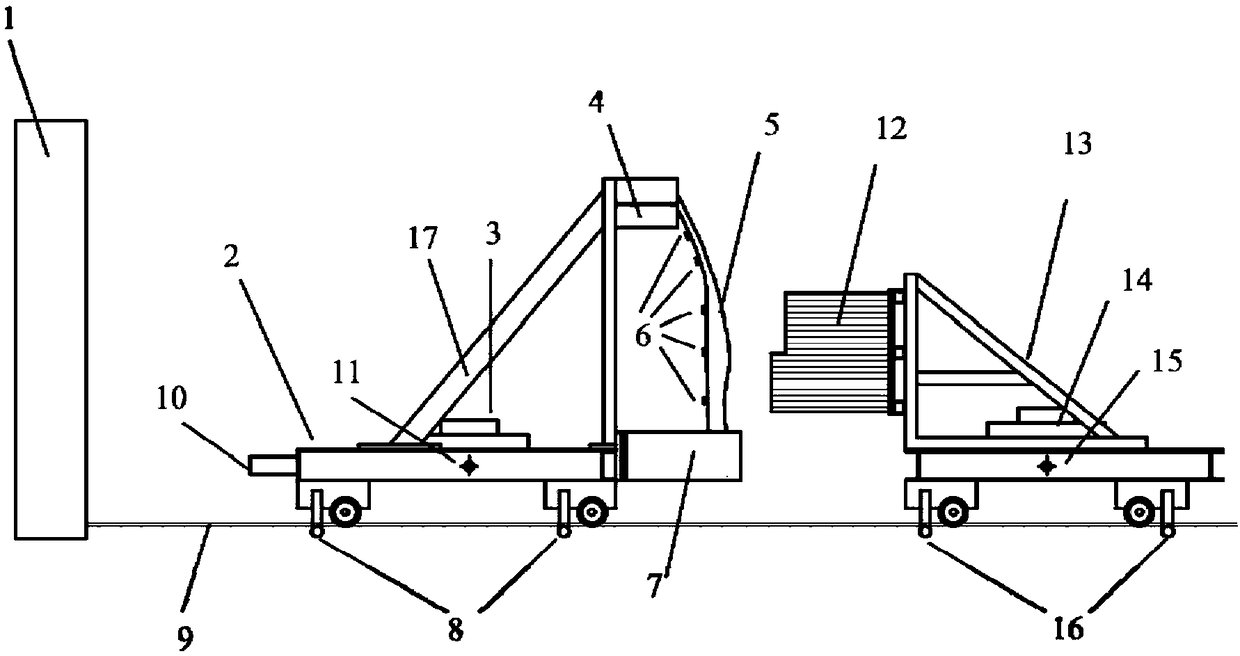
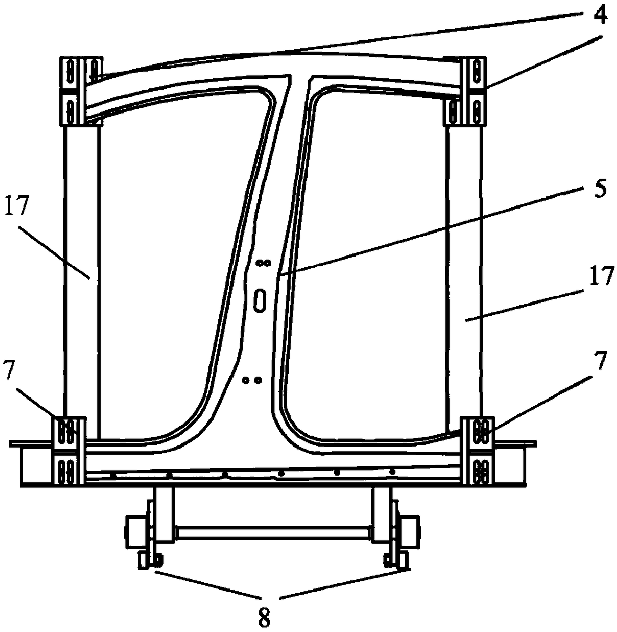
[0030] A B-pillar assembly component level crash test device, such as Figure 1~2 As shown, it includes a rigid wall 1, a bumped trolley 2 and a collision trolley 13. The bumped trolley 2 is used for rigid connection with the B-pillar assembly 5, and the collision trolley 13 and the bumped trolley 2 are installed on the same guide rail 9 Among them, a buffer mechanism is provided between the impacted trolley 2 and the rigid wall 1, and the collision trolley 13, the impacted trolley 2 and the rigid wall 1 are arranged in sequence according to the initial velocity direction of the collision trolley 13.

[0031] In this embodiment, the B-pillar assembly 5 includes the B-pillar and the B-pillar assembly upper side beam connected to the B-pillar and the B-pillar assembly threshold beam. And the lower fixed plate 7 of the B-pillar assembly, and the counterweight 3 of the bumped trolley is arranged, the buffer mechanism 10 and the coupler wheel 8 of the bumped chassis are installed, ...


PUM


Abstract

The invention relates to a B-pillar assembly part-level collision test device and a test method thereof. The device comprises a rigid wall, a collided trolley and a collision trolley, wherein the collided trolley is used for being rigidly connected with the B-pillar assembly, the collision trolley and the collided trolley are arranged in a same guide rail, a buffer mechanism is arranged between the collided trolley and the rigid wall, and the collision trolley, the collided trolley and the rigid wall are sequentially arranged according to the initial speed direction of the collision trolley. Compared with the prior art, the deformation behavior of the B-pillar assembly obtained by using the method is matched with the deformation behavior of the B-pillar assembly obtained by the collision test of a whole vehicle, so that the high-cost collision test of the whole vehicle can be avoided, the performance data of the B-pillar assembly matched with the collision of the whole vehicle can be provided, thereby being beneficial to more efficiently evaluating the performance of the B-pillar assembly, optimizing the design, shortening the development period and reducing the test cost.

Description

technical field [0001] The invention belongs to the technical field of auto parts test equipment, and relates to a B-pillar assembly part-level impact test device and a test method, in particular to a B-pillar assembly part-level impact equivalent to the vehicle-level side impact behavior Test device and test method. Background technique [0002] my country's auto industry has developed rapidly, and its production and sales of automobiles have ranked first in the world for many years. Cars have greatly facilitated the lives of Chinese people, but traffic accidents have also occurred frequently, so the safety of cars is extremely important. At the same time, under the background of global calls for energy conservation and emission reduction, energy conservation and emission reduction is regarded as an important task for the transformation and upgrading of industrial enterprises, and automobile lightweight is responsible for energy conservation and emission reduction in the a...

Claims


Application Information

Patent Timeline
Patent Type & Authority Applications(China)
IPC IPC(8): G01M7/08G01M17/007
CPCG01M7/08G01M17/007
Inventor 林建平林野路洪洲郭爱民李永记
Owner TONGJI UNIV
Why Eureka
Try Eureka