Camera pose estimation method, system, device and storage medium

A pose estimation and camera technology, applied in the field of positioning and tracking, can solve the problems of large intersection error and low pose estimation accuracy, and achieve the effect of improving accuracy

Active Publication Date: 2021-03-09
丰翼科技(深圳)有限公司
View PDF4 Cites 0 Cited by
  • Summary
  • Abstract
  • Description
  • Claims
  • Application Information

AI Technical Summary

Problems solved by technology

[0007] The conventional PnP algorithm relies on matching with feature points. When there are few feature points, the accuracy of pose estimation is not high.
[0008] The existing PnPL algorithm converts straight line matching into point matching, requiring at least two straight lines, and the straight lines must intersect. When the straight lines are close to parallel, the error of the intersection point will be large

Method used


Image

  • Camera pose estimation method, system, device and storage medium
  • Camera pose estimation method, system, device and storage medium
  • Camera pose estimation method, system, device and storage medium

Examples


Embodiment Construction

[0032] The specific embodiments of the present invention are used to illustrate the present invention, but are not limited to the specific embodiments.

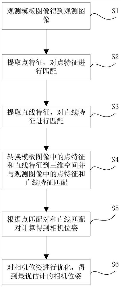
[0033] figure 1 It is an overall flowchart of the camera pose estimation method according to the embodiment of the present invention;

[0034] Such as figure 1 As shown, the camera pose estimation method of the embodiment of the present invention includes the following steps:

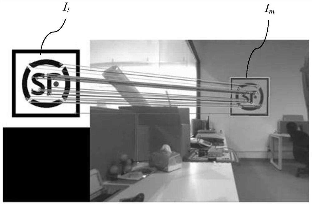
[0035] In step S1, the observation image is obtained by observing the selected template image with the camera.

[0036] First, select a template image I m , the size of the template is known, let the actual physical width and height of the template be W p , H p , the unit is meter; set the width and height of the template image as W m , H m , whose unit is pixel.

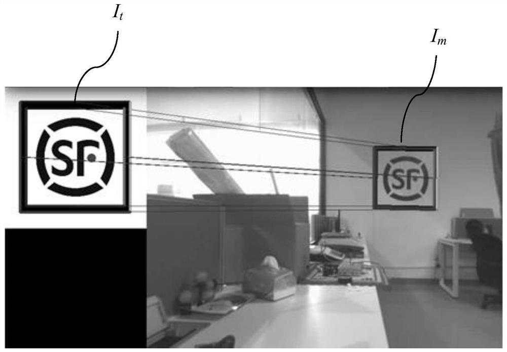
[0037] Then use the camera to observe the selected template image I m , get the observed image I t .

[0038] Step S2, extracting point features in the template image and the obse...


PUM


Abstract

The invention provides a camera pose estimation method, comprising the following steps: Obtaining an observation image through a template image selected by camera observation; respectively extracting point features and straight line features in the template image and the observation image; Features and line features for feature matching; convert the 2D points and lines in the template image to 3D space, obtain the 3D point features and 3D line features of the template image, and form 3D‑2D with the point features and line features in the observation image Point matching pairs and line matching pairs of 3D‑2D point matching pairs and line matching pairs are used to calculate the camera pose. The camera pose estimation method of the present invention directly uses straight line matching to construct constraints instead of converting to point matching, so that there is no limitation of straight line parallelism, and only one straight line can also be used to estimate together with point features, fusing point features and line features, Improve the accuracy of PnP position estimation.

Description

technical field [0001] The invention relates to the field of positioning and tracking, in particular to a camera pose estimation method. Background technique [0002] Camera pose estimation is a classic problem in computer vision. It is known that some 3D coordinate points in 3D space and their 2D projection coordinates on the camera image are used to estimate the position and attitude of the camera in 3D space. One of the most common applications of camera pose estimation is external parameter calibration in camera calibration. External parameter calibration takes checkerboard images through the camera, and after calibrating the internal parameters of the camera (focal length, optical center, distortion coefficient), estimate the camera of each image. 3D position and 3D pose relative to the checkerboard. [0003] The most commonly used method in camera pose estimation is PnP (Perspective n Points) and its series of improved algorithms. This method first associates the 3D c...

Claims


Application Information

Patent Timeline
Patent Type & Authority Patents(China)
IPC IPC(8): G06T7/73G06K9/62
CPCG06T7/73G06T2207/10012G06F18/22
Inventor 毛曙源
Owner 丰翼科技(深圳)有限公司
Why Eureka
Try Eureka