Movement track

A technology for moving rails and guide rails, applied in the field of rails, can solve problems such as difficulty, waste of manpower, waste of material resources, etc., and achieve the effect of preventing slippage

Pending Publication Date: 2019-03-22
合肥瑞堡科技发展有限公司
View PDF0 Cites 1 Cited by
  • Summary
  • Abstract
  • Description
  • Claims
  • Application Information

AI Technical Summary

Problems solved by technology

[0002] In the prior art, when the device is moved back and forth, in order to save floor space, the device is installed on the endless conveyor belt that moves back and forth, but it is more difficult when the endless conveyor belt is installed on the driving wheel and the driven wheel. It takes a lot of manpower, and a part of the installation space needs to be reserved in the design, so that after installation, pressure rollers or other equipment are needed to remove the tension of the reserved part of the conveyor belt, and the conveyor belt will still slack during the transmission process. It is inconvenient to adjust, and sometimes the product needs to be customized according to the needs of customers. When the existing endless conveyor belt is shorter or longer, it still needs to be purchased separately, which greatly wastes material costs, so a moving track is urgently needed to solve this problem.

Method used


Image

  • Movement track
  • Movement track
  • Movement track

Examples


Embodiment Construction

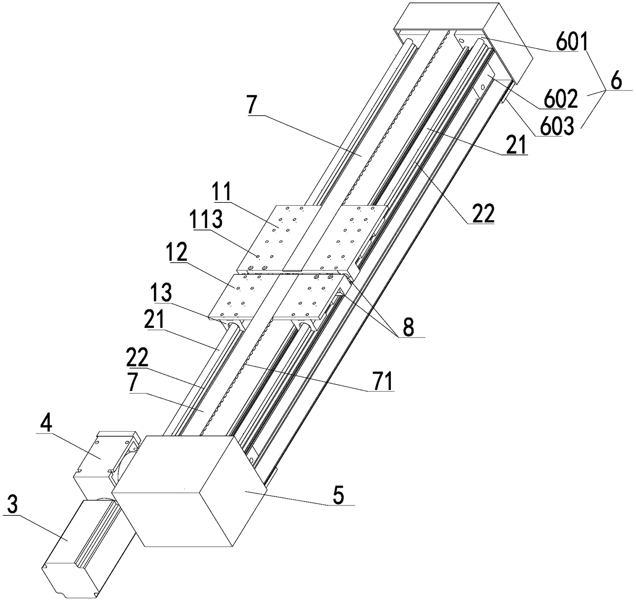
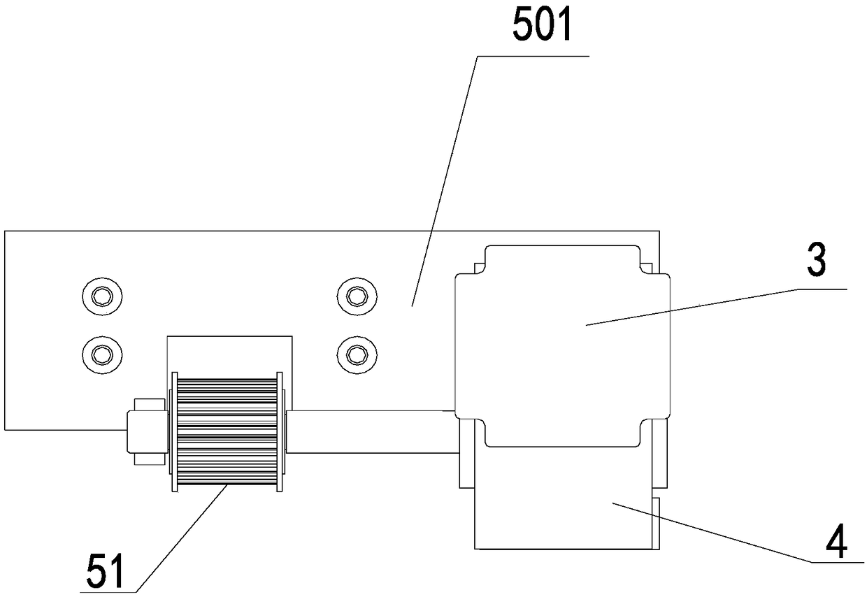
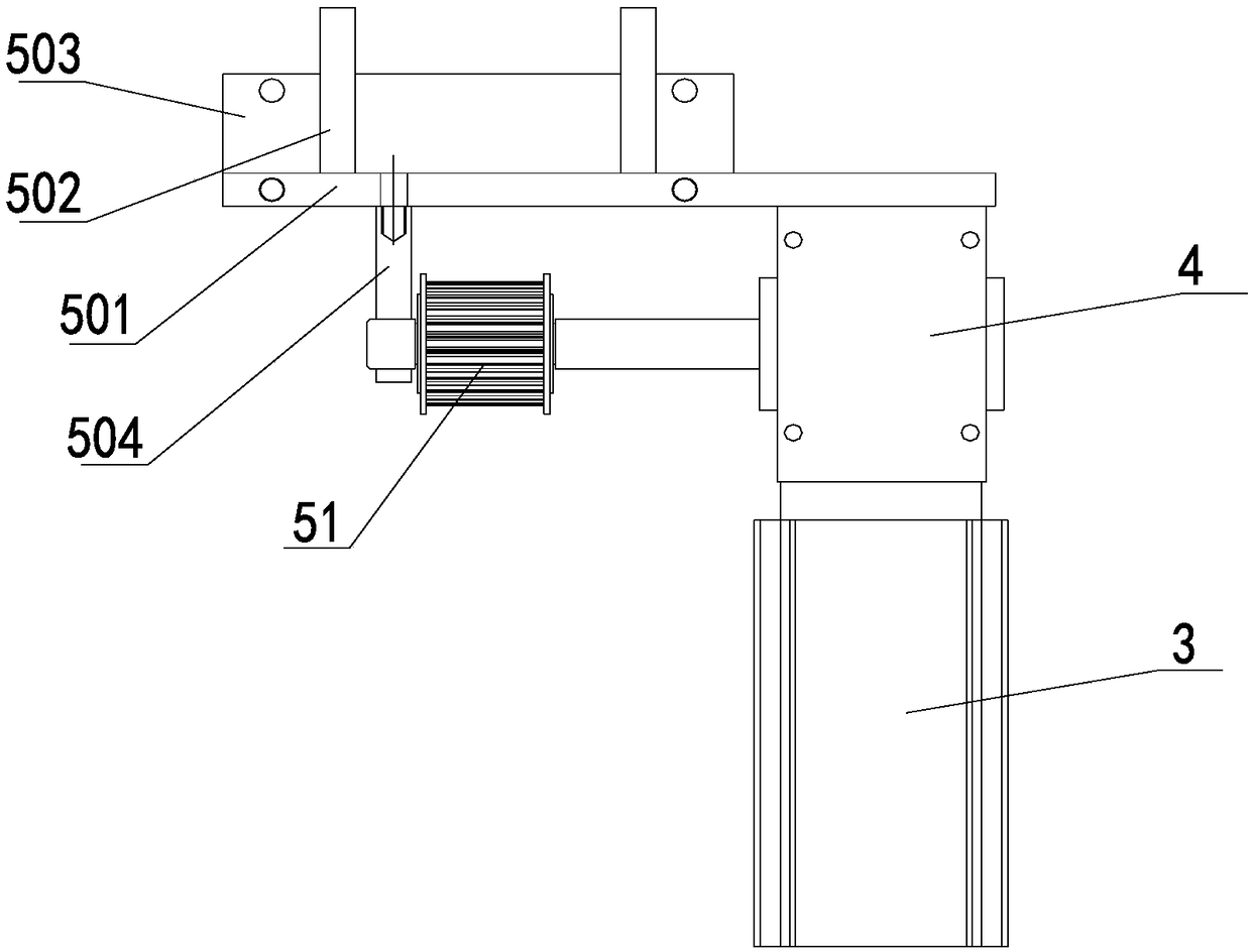
[0035] like Figure 1-4 As shown, a moving track includes a base, a conveyor belt, a power mechanism, a first mounting plate 11 and a second mounting plate 12 , and connectors. The power mechanism includes a motor 3 and a reduction box 4 . The base is arranged vertically. In order to save cost, the base is fixed and formed by two parallel I-beams in the length direction. The conveyor belt can be a chain, a timing belt 7, or a conveyor belt, and the timing belt 7 is taken as an example here.

[0036] The synchronous belt 7 is supported in a ring shape by the first support member 5 and the second support member 6, the upper surface of the ring shape is disconnected, and the two ends of the disconnection are respectively fixed on the first mounting plate 11 and the second mounting plate 12, the first mounting plate 11 and the second mounting plate 12 are provided with screw positioning holes 8, the screw positioning holes 8 on the first mounting plate 11 and the second mounting...


PUM


Abstract

The invention belongs to the field of machines, and particularly relates to a movement track. The movement track comprises a conveying belt, a first mounting plate and a second mounting plate. A synchronous belt is supported by a first supporting part and a second supporting part to form a ring, wherein the upper surface of the ring is in a disconnected state. The two ends of the disconnected position are fixed to the first mounting plate and the second mounting plate separately, and the first mounting plate and the second mounting plate are connected through a connecting piece. The distance between the first mounting plate and the second mounting plate can be adjusted through the connecting piece. The movement track has the advantages that as being disconnected, the ring-shaped conveyingbelt can be installed on the supporting parts conveniently; and as the disconnected position of the conveying belt is installed on the first mounting plate and the second mounting plate, the distancebetween the first mounting plate and the second mounting plate can be adjusted through the connecting piece, so that the degree of tightness of the conveying belt is adjusted without replacing the conveying belt.

Description

technical field [0001] The invention relates to the track field, in particular to a moving track. Background technique [0002] In the prior art, when the device is moved back and forth, in order to save floor space, the device is installed on the endless conveyor belt that moves back and forth, but it is more difficult when the endless conveyor belt is installed on the driving wheel and the driven wheel. It takes a lot of manpower, and a part of the installation space needs to be reserved in the design, so that after installation, pressure rollers or other equipment are needed to remove the tension of the reserved part of the conveyor belt, and the conveyor belt will still slack during the transmission process. It is inconvenient to adjust, and sometimes the product needs to be customized according to the needs of customers. When the existing endless conveyor belt is shorter or longer, it still needs to be purchased separately, which greatly wastes material costs, so a movi...

Claims


Application Information

Patent Timeline
Patent Type & Authority Applications(China)
IPC IPC(8): B65G35/00
CPCB65G35/00
Inventor 范卫国
Owner 合肥瑞堡科技发展有限公司
Why Eureka
Try Eureka