Heat tube with distance optimizing design

A heat pipe and distance technology, applied in indirect heat exchangers, lighting and heating equipment, etc., can solve the problems of low heat pipe efficiency, uneven heat exchange, low heat exchange coefficient, etc., to improve heating efficiency, improve utilization efficiency, strengthen heat transfer effect

Active Publication Date: 2019-03-22
泰达纺织泰州有限公司
View PDF4 Cites 5 Cited by
  • Summary
  • Abstract
  • Description
  • Claims
  • Application Information

AI Technical Summary

Problems solved by technology

[0004] The heat pipes in the prior art are in a static state during the heat exchange process, relying only on the heat dissipation at the condensing end of the heat pipe, the improvement of many inventions is only the improvement of the heat transfer enhancement structure at the condensing end
On the other hand, in the prior art, different heating powers are not used for different positions of the heat pipe, resulting in low efficiency of the heat pipe
[0005] In view of the above problems, the present invention provides a new heat pipe, so as to solve the problems of low heat transfer coefficient and uneven heat transfer in the case of heat pipe heat exchange

Method used


Image

  • Heat tube with distance optimizing design
  • Heat tube with distance optimizing design
  • Heat tube with distance optimizing design

Examples


Embodiment Construction

[0045] The specific embodiments of the present invention will be described in detail below in conjunction with the accompanying drawings.

[0046] In this article, if there is no special explanation, when it comes to formulas, " / " means division, and "×" and "*" mean multiplication.

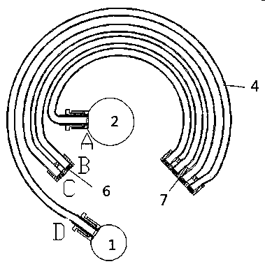
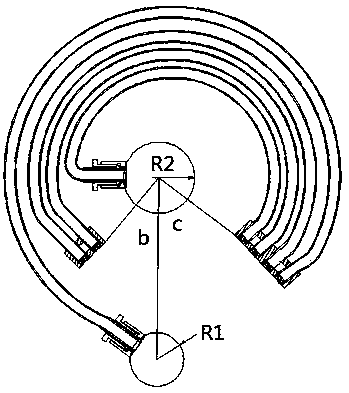
[0047] It is an object of the present invention to provide an electrically heated heat pipe such as Figure 4 -6 shown.

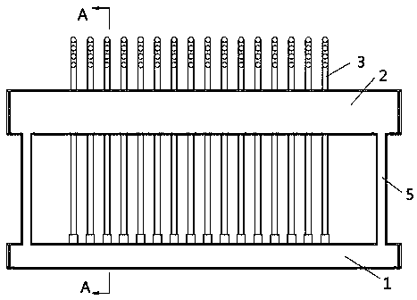
[0048] A heat pipe, comprising a lower tube box 1, an upper tube box 2, a heat exchange tube bundle and a return tube 5, the heat exchange tube bundle communicates with the lower tube box 1 and the upper tube box 2, and the lower tube box 1 is an evaporation end , the condensing end includes the upper tube box 2, the fluid absorbs heat and evaporates in the lower tube box 1, condenses in the upper tube box 2, and the condensed fluid returns to the lower tube box 1 through the return pipe; the return tube is connected to the lower tube box 1 and the positions of both sides of...


PUM


Abstract

The invention provides a heat tube. The heat tube comprises a lower tube box, an upper tube box, a heat exchange tube bundle and a reflow tube, wherein the heat exchange tube bundle communicates withthe lower tube box and the upper tube box; the lower tube box is an evaporating end; a condensing end comprises the upper tube box; fluid absorbs heat in the lower tube box to evaporate, and is condensed in the upper tube box; condensed fluid returns to the lower tube box through the reflow tube; the reflow tube is connected to the positions of two side end parts of the lower tube box and the lower tube box; an electric heating device is arranged in the lower tube box; a distance from the lower tube box to the centre of the upper tube box is L, and a distance between adjacent heat exchange tubes is M, M is equal S(L), and S'(L) is greater than 0. Through the optimizing setting, heat exchange efficiency is further improved, and heat distribution uniformity of heat exchange is improved.

Description

technical field [0001] The invention belongs to the field of heat pipes, in particular to a coil heat pipe. Background technique [0002] Heat pipe technology is a heat transfer element called "heat pipe" invented by George Grover of Los Alamos National Laboratory in the United States in 1963. It makes full use of the principle of heat conduction and phase change medium. The rapid heat transfer properties of the heat pipe quickly transfer the heat of the heating object to the heat source, and its thermal conductivity exceeds that of any known metal. [0003] Heat pipe technology was widely used in aerospace, military and other industries before. Since it was introduced into the radiator manufacturing industry, people have changed the traditional radiator design ideas and got rid of the single heat dissipation mode that only relies on high air volume motors to obtain better heat dissipation. The use of heat pipe technology enables the radiator to obtain a satisfactory heat e...

Claims


Application Information

Patent Timeline
Patent Type & Authority Applications(China)
IPC IPC(8): F28D15/02F28D15/06
CPCF28D15/02F28D15/025F28D15/06
Inventor 赵炜徐建军
Owner 泰达纺织泰州有限公司
Why Eureka
Try Eureka