Liquid-cooling power battery with battery box with immersed external bottom face

A technology for power batteries and battery boxes, which is applied in the field of power battery thermal management systems, can solve problems such as increased thermal resistance and complex thermal management structures, and achieve the effects of high thermal efficiency, high safety, and flexible configuration

Active Publication Date: 2019-03-22
开沃新能源汽车集团股份有限公司
View PDF3 Cites 2 Cited by
  • Summary
  • Abstract
  • Description
  • Claims
  • Application Information

AI Technical Summary

Problems solved by technology

The thermal management of the side of the battery cell belongs to the thermal management in the battery box, and its thermal management structure is more complicated. In the case of cha

Method used


Image

  • Liquid-cooling power battery with battery box with immersed external bottom face
  • Liquid-cooling power battery with battery box with immersed external bottom face
  • Liquid-cooling power battery with battery box with immersed external bottom face

Examples


Embodiment Construction

[0016] The present invention will be further described below in conjunction with the accompanying drawings.

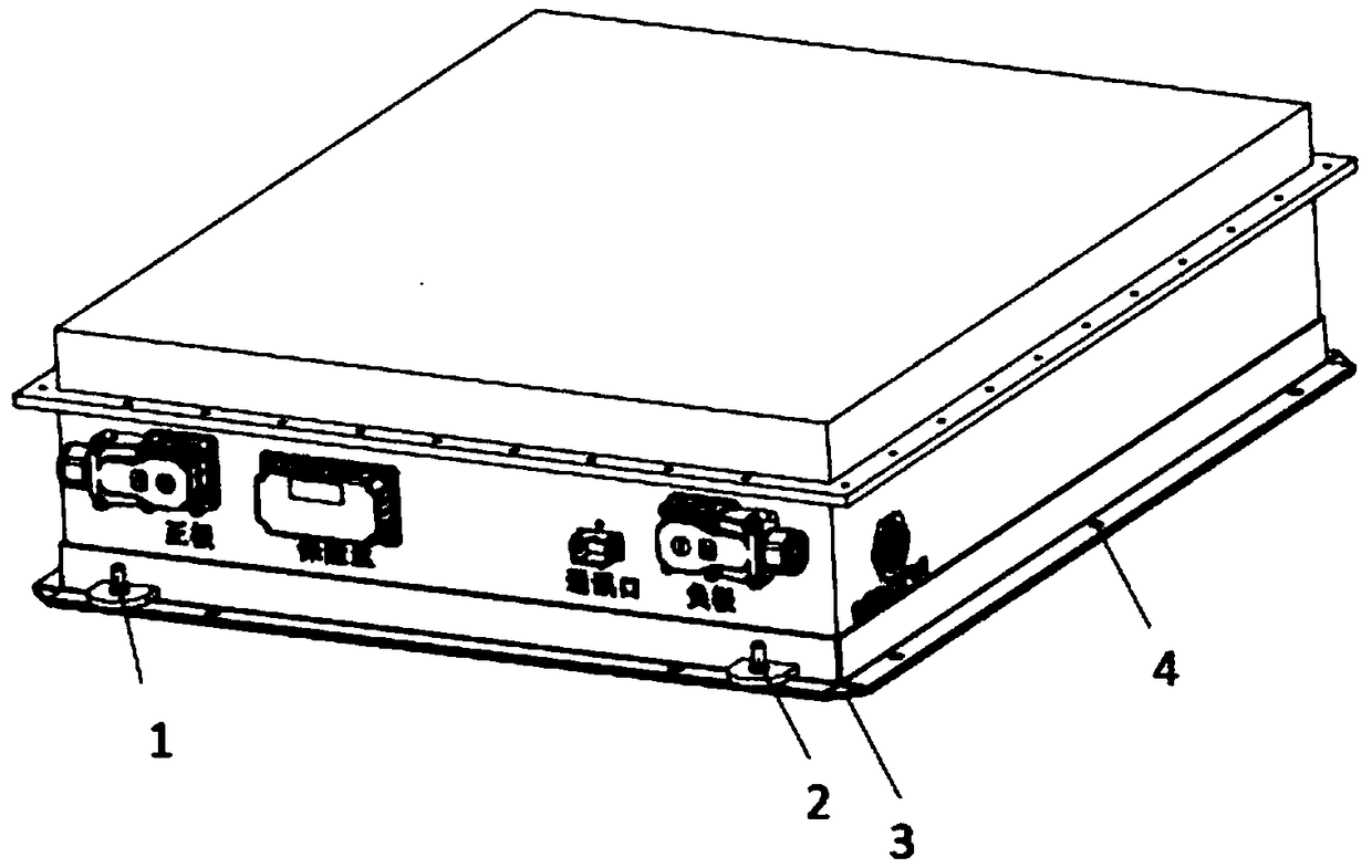
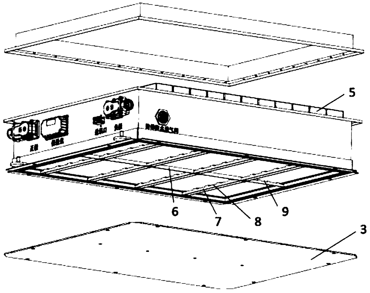
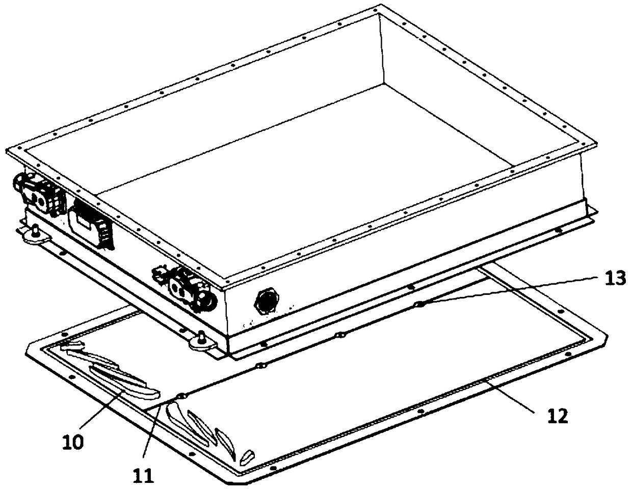
[0017] The submerged liquid-cooled power battery on the outer bottom of the battery box of the present invention includes a liquid inlet joint 1, a liquid outlet joint 2, a sealing support plate 3, a bolt hole 4, a single battery cell 5, a flow partition plate 6, a shunt type reinforcement rib 7, a reinforcement Rib runner 8, flow divider flow channel 9, liquid outlet 14, liquid inlet 15, seal bolt hole 16 of flow divider, and sealing platform 17 on the bottom surface of the battery box. The liquid inlet joint 1 and the liquid outlet joint 2 are located above the sealing support plate 3, the liquid inlet joint 1 is used for connecting with the inlet pipeline of the liquid heat management medium, and the liquid outlet joint 2 is used for connecting with the outlet pipeline of the liquid heat management medium. The sealing support plate 3 is combined with the bottom of t...


PUM


Abstract

The invention discloses a liquid-cooling power battery with a battery box with immersed external bottom face. The liquid-cooling power battery comprises a liquid inlet joint, a liquid outlet joint, asealing supporting plate, bolt holes, a monomer battery cell, a baffle plate, divided-flow reinforcing ribs, reinforcing rib flow passages, a baffle plate flow passage, a liquid outlet, a liquid inlet, baffle plate sealing bolt holes and a battery box bottom face sealing table, wherein the liquid inlet joint and the liquid outlet joint are positioned above the sealing supporting plate; the liquidinlet joint is connected with a liquid heat management medium inlet pipeline; the liquid outlet joint is connected with a liquid heat management medium outlet pipeline; the sealing supporting plate iscombined with the bottom of the power battery box to form a sealed cavity; the bolt holes are formed in the periphery of the sealing supporting plate; the baffle plate is positioned at the bottom ofthe battery box to make liquid in the bottom face of the battery box divided into inflowing liquid and outflowing liquid; divided-flow reinforcing ribs are positioned at the bottom of the battery box,and is perpendicular to the baffle plate; reinforcing rib flow passages are arranged on the divided-flow reinforcing ribs; and the baffle plate flow passage is arranged on the baffle plate. Accordingto the invention, the flexible configuration of the power battery with or without heat management can be achieved.

Description

Technical field: [0001] The invention relates to a power battery thermal management system, in particular to a submerged liquid-cooled power battery on the outer bottom of a battery box. Background technique: [0002] As one of the core components of electric vehicles, power batteries are inseparable from their performance and battery thermal management. The purpose of power battery thermal management is to take appropriate measures to make the single battery work in a suitable temperature range and ensure the uniform temperature distribution of the battery pack. As one of the battery thermal management methods, the liquid medium thermal management method has good heat exchange efficiency, high sealing level of the battery box, and can realize heating and cooling of the battery, so it is generally recognized by everyone and widely used. [0003] The thermal management of power battery liquid medium can be divided into many forms. According to the liquid medium, it can be d...

Claims


Application Information

Patent Timeline
IPC IPC(8): H01M2/10H01M10/613H01M10/6568H01M50/249
CPCH01M10/613H01M10/6568H01M2220/20H01M50/20Y02E60/10
Inventor 黄永阔
Owner 开沃新能源汽车集团股份有限公司
Why Eureka
Try Eureka