Working mode switching method and device for conversion circuit, and boost-buck converter

A technology for converting circuits and working modes, which is applied in the direction of output power conversion device, adjustment of electrical variables, conversion of DC power input to DC power output, etc., to achieve the effect of stable switching

Pending Publication Date: 2019-03-22
ZTE CORP
View PDF10 Cites 0 Cited by
  • Summary
  • Abstract
  • Description
  • Claims
  • Application Information

AI Technical Summary

Problems solved by technology

[0004] The main purpose of the present invention is to propose a working mode switching method, device and buck-boost converter of a conversion circuit, which solves the problem of the DC conversion circuit switching back and forth between various working modes

Method used


Image

  • Working mode switching method and device for conversion circuit, and boost-buck converter
  • Working mode switching method and device for conversion circuit, and boost-buck converter
  • Working mode switching method and device for conversion circuit, and boost-buck converter

Examples


no. 1 example

[0045] In the first embodiment of the present invention, a working mode switching method of a conversion circuit is applied to a buck-boost converter, such as Figure 4 As shown, the method specifically includes the following steps:

[0046] Step S401: Obtain the duty cycle value of the first circuit in the direct current DC conversion circuit.

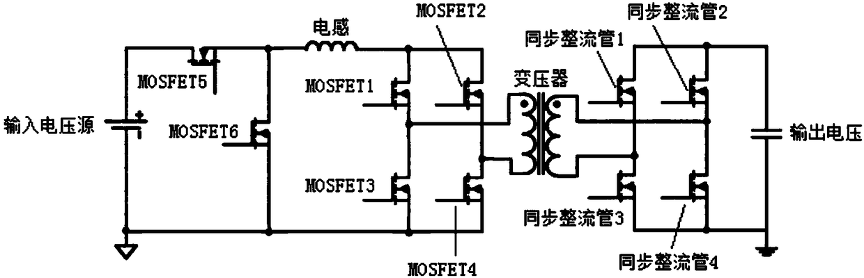
[0047] Specifically, when the DC conversion circuit is as figure 1 In the isolated BUCK-BOOST circuit shown, if the front stage is a BUCK switch circuit and the rear stage is an isolated BOOST circuit, the first circuit is an isolated BOOST circuit.

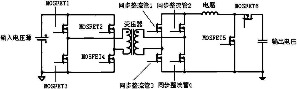
[0048] When the DC conversion circuit is as figure 2 In the isolated BUCK-BOOST circuit shown, if the front stage is an isolated BUCK circuit and the rear stage is a BOOST switch circuit, the first circuit is an isolated BUCK circuit.

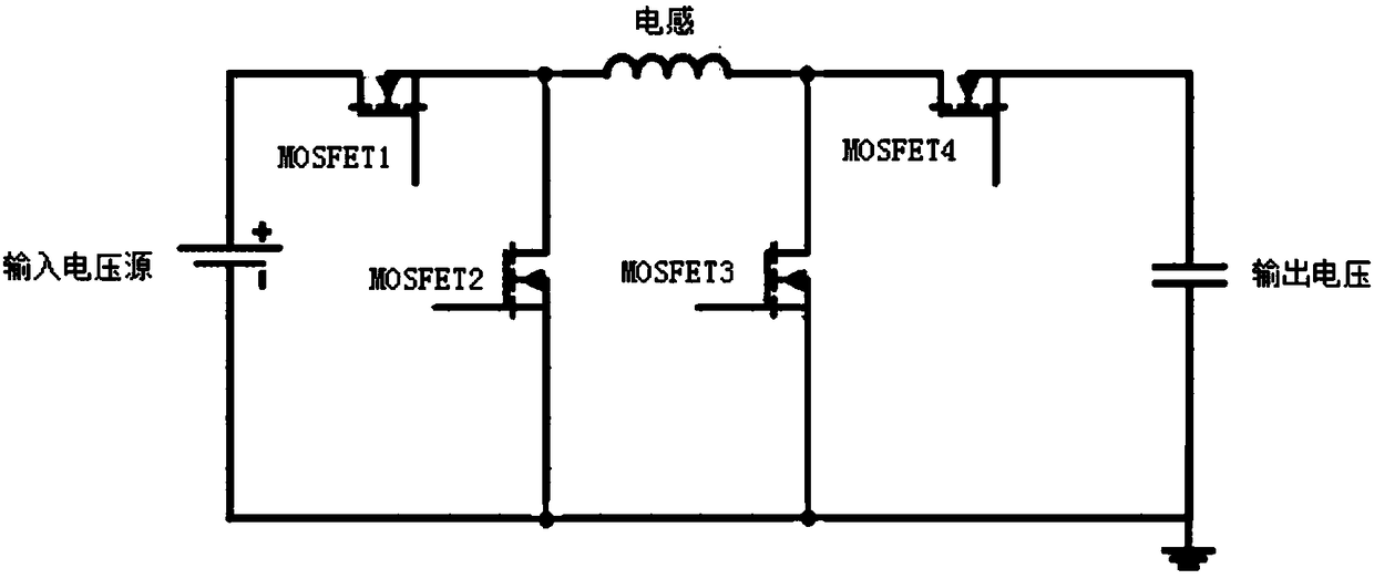
[0049] When the DC conversion circuit is as image 3 In the BUCK-BOOST circuit shown, if the front stage is a BUCK switch circuit and the rear stage...

no. 2 example

[0071] In the second embodiment of the present invention, an operating mode switching device for a conversion circuit is applied to a buck-boost converter, such as Figure 5 As shown, the device specifically includes the following components:

[0072] 1) An acquisition module 501, configured to acquire the duty cycle value of the first circuit in the direct current DC conversion circuit.

[0073] Specifically, when the DC conversion circuit is as figure 1 In the isolated BUCK-BOOST circuit shown, if the front stage is a BUCK switch circuit and the rear stage is an isolated BOOST circuit, the first circuit is an isolated BOOST circuit.

[0074] When the DC conversion circuit is as figure 2 In the isolated BUCK-BOOST circuit shown, if the front stage is an isolated BUCK circuit and the rear stage is a BOOST switch circuit, the first circuit is an isolated BUCK circuit.

[0075] When the DC conversion circuit is as image 3 In the BUCK-BOOST circuit shown, if the front stage...


PUM


Abstract

The invention introduces a working mode switching method and device for a conversion circuit, and a boost-buck converter. The method includes the following steps: acquiring the duty ratio value of a first circuit in a direct current DC conversion circuit; comparing the duty ratio value of the first circuit with a preset threshold, and setting the duty ratio value of a second circuit in the DC conversion circuit according to the comparison result; and switching the working mode of the DC conversion circuit according to the set duty ratio value of the second circuit. The problem on how to switcha DC conversion circuit between various working modes is solved, and stable switching of a DC conversion circuit between working modes is ensured.

Description

technical field [0001] The invention relates to the technical field of power electronics, in particular to a working mode switching method and device for a conversion circuit and a buck-boost converter. Background technique [0002] In the field of power electronics technology, especially the DC (Direct Current, direct current) conversion circuit in the buck-boost converter, it can be as figure 1 , figure 2 , image 3 Any of the three types of conversion circuits shown. Such as figure 1 The DC conversion circuit shown is an isolated BUCK-BOOST circuit, and the front stage is a BUCK switch circuit, and the rear stage is an isolated BOOST circuit. Among them, the duty cycle of the BUCK switch circuit is 0%-100%, and the duty cycle of the full-bridge switch on the primary side of the post-stage BOOST circuit is always greater than 50%. When the duty cycle of the BUCK switch circuit is less than 100%, figure 1 The isolated BUCK-BOOST circuit shown actually works in the BU...

Claims


Application Information

Patent Timeline
Patent Type & Authority Applications(China)
IPC IPC(8): H02M3/335H02M3/158
CPCH02M3/1582H02M3/33592
Inventor 胡永辉
Owner ZTE CORP
Why Eureka
Try Eureka