Steel pipe cutting machine

A technology for cutting machines and steel pipes, which is applied in the direction of pipe shearing devices, shearing devices, and attachments of shearing machines, etc., which can solve the problems of inconvenient steel pipe connection protection, inconvenient uniform cutting, and difficult steel pipe protection, so as to avoid the amount of cutting Excessive size, improved cutting quality, and wide application range

Pending Publication Date: 2019-03-26
HUAQIAO UNIVERSITY
View PDF0 Cites 3 Cited by
  • Summary
  • Abstract
  • Description
  • Claims
  • Application Information

AI Technical Summary

Problems solved by technology

[0002] Existing steel pipe cutting machines are divided into planetary cutting machines, hydraulic cutting machines, external card cutting machines, CNC hydraulic cutting machines, electric cutting machines, pneumatic cutting machines and other models, but the existing cutting machines generally need to be refurbished It is not convenient to use the clamp alone to tighten the steel pipe, and when cutting the steel pipe, only one surface is cut, which is easy to increase the wear of the cutting blade. When the steel pipe needs to be rotated, the clamp needs to be adjusted. Trouble, it is inconvenient to cut uniformly while rotating the steel pipe, and when the existing steel pipe is cut, generally only a single steel pipe is cut, it is inconvenient to cut multiple steel pipes at the same time, which affects the cutting efficiency, and the existing When clamping steel pipes, different clamps are required to tighten steel pipes of different thicknesses, which is more troublesome. After cutting the steel pipes, it is also inconvenient to protect the cut steel pipes, and it is easy to make the steel pipes fall directly to the ground. On, it is not easy to protect the steel pipe

Method used


Image

  • Steel pipe cutting machine
  • Steel pipe cutting machine
  • Steel pipe cutting machine

Examples


Embodiment Construction

[0022] In order to further explain the technical solution of the present invention, the following will be described in detail in conjunction with the examples.

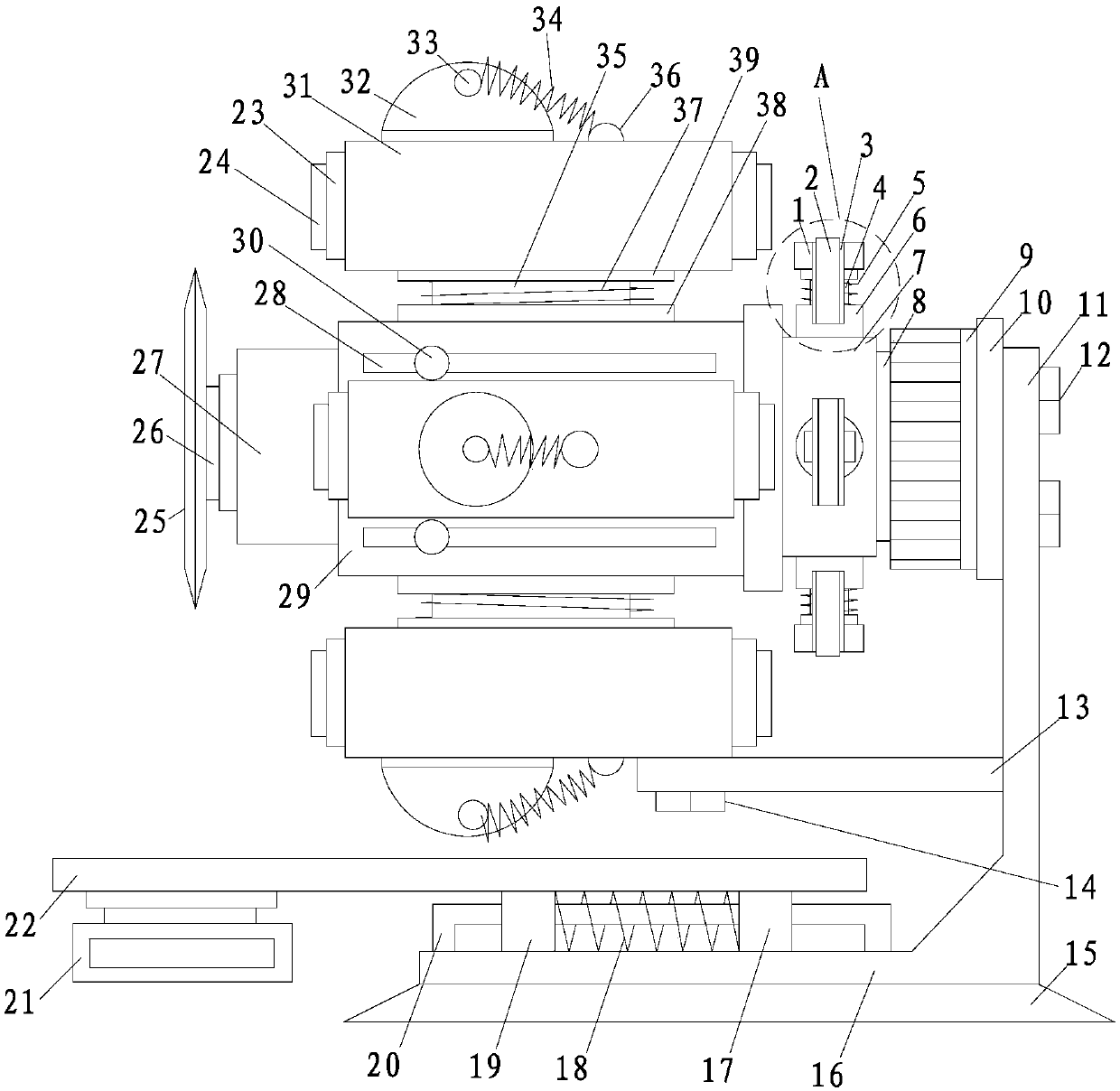
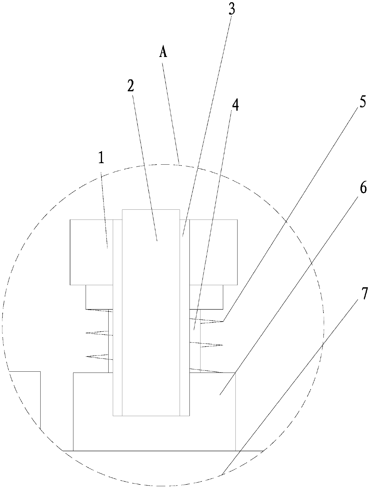
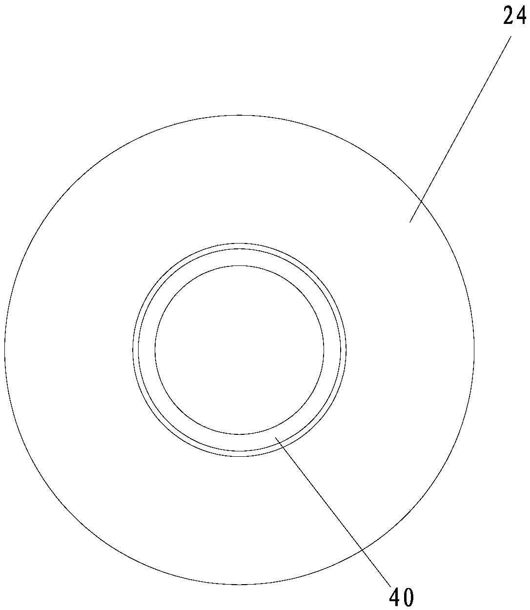
[0023] refer to Figure 1 to Figure 3 , a steel pipe cutting machine, comprising a frame, a first motor 9 mounted on the frame, a drum 7 connected to the output end of the first motor 9, a friction assembly for the steel pipe 40 to abut against and drive the steel pipe 40 to rotate , the installation cylinder 29 fitted in the rotating cylinder 7, the sleeve 31 arranged on the installation cylinder 29, the rotating tube 23 rotatably arranged in the sleeve 31, the first air bag 24 arranged in the rotating tube 23, The air supply mechanism for supplying air to the first air bag 24, the second motor 27 slidably installed in the installation cylinder 29, and the cutting disc 25 connected with the output shaft of the second motor 27, the first motor 9 The output shaft, the rotating cylinder 7 and the installation cylinder ...


PUM


Abstract

The invention relates to a steel pipe cutting machine. The steel pipe cutting machine comprises a rack, a first motor, a rotating drum, friction assemblies, an installing drum rotatably arranged in the rotating drum in a matched mode, sleeves, a rotating pipe, a first air bag arranged in the rotating pipe, an air supplying mechanism used for supplying air to the first air bag, a second motor slidably installed in the installing drum and a cutting disc which is in transmission connection with an output shaft of the second motor; an output shaft of the first motor, the rotating drum and the installing drum are coaxially arranged; the sleeves and the installing drum are arranged in parallel; the first air bag is shaped like a cylinder and provided with a channel used for allowing a steel pipeto penetrate; and sleeves are connected to the rack. According to the steel pipe cutting machine, rotating fit between the rotating pipe and the sleeves is skillfully utilized, rotation of the friction assemblies (particularly, friction layers) on the steel pipe is combined, therefore, the steel pipe needing to be cut can rotate, the steel pipe is cut in the rotating process, uniform cutting canbe conducted, the cutting quality is improved, and meanwhile the cutting disc can be better protected.

Description

technical field [0001] The invention relates to a steel pipe cutting machine. Background technique [0002] Existing steel pipe cutting machines are divided into planetary cutting machines, hydraulic cutting machines, external card cutting machines, CNC hydraulic cutting machines, electric cutting machines, pneumatic cutting machines and other models, but the existing cutting machines generally need to be refurbished It is not convenient to use the clamp alone to tighten the steel pipe, and when cutting the steel pipe, only one surface is cut, which is easy to increase the wear of the cutting blade. When the steel pipe needs to be rotated, the clamp needs to be adjusted. Trouble, it is inconvenient to cut uniformly while rotating the steel pipe, and when the existing steel pipe is cut, generally only a single steel pipe is cut, it is inconvenient to cut multiple steel pipes at the same time, which affects the cutting efficiency, and the existing When clamping steel pipes, d...

Claims


Application Information

Patent Timeline
Patent Type & Authority Applications(China)
IPC IPC(8): B23D21/00B23D33/02B23D33/00
CPCB23D21/00B23D33/00B23D33/02
Inventor 童江王兴技肖朝昀涂兵雄赵紫薇
Owner HUAQIAO UNIVERSITY
Why Eureka
Try Eureka