Aluminum die casting machining device and method and aluminum die casting

An aluminum die-casting and processing equipment technology, applied in the field of aluminum die-casting products, can solve the problems of increasing equipment and operation complexity, low processing efficiency of through-hole chamfering, inability to handle, etc., to achieve processing efficiency, simplify equipment and space. compact effect

Pending Publication Date: 2019-03-26
宁波爱柯迪精密部件有限公司
View PDF0 Cites 0 Cited by
  • Summary
  • Abstract
  • Description
  • Claims
  • Application Information

AI Technical Summary

Problems solved by technology

[0004] The above-mentioned internal chamfering treatment is performed twice on both sides of the through hole of the aluminum die casting; either by adjusting the direction of the aluminum die casting or adjusting the direction of the tool to achieve double-sided chamfering; this will increase the complexity of equipment and operations; at the same time The processing efficiency of the through-hole chamfering of aluminum die-casting parts is relatively low; in addition, when there is an interfering part on the other side of the through-hole on the aluminum die-casting part, the tool cannot chamfer the through-hole from the other direction due to the interfering part. deal with

Method used


Image

  • Aluminum die casting machining device and method and aluminum die casting
  • Aluminum die casting machining device and method and aluminum die casting
  • Aluminum die casting machining device and method and aluminum die casting

Examples


Embodiment Construction

[0037] Preferred embodiments of the present invention will be described in detail below with reference to the accompanying drawings. Those skilled in the art will appreciate that these descriptions are only descriptive and exemplary, and should not be construed as limiting the protection scope of the present invention.

[0038] Aluminum die castings include automotive components such as wiper skeletons and automotive gearbox housings.

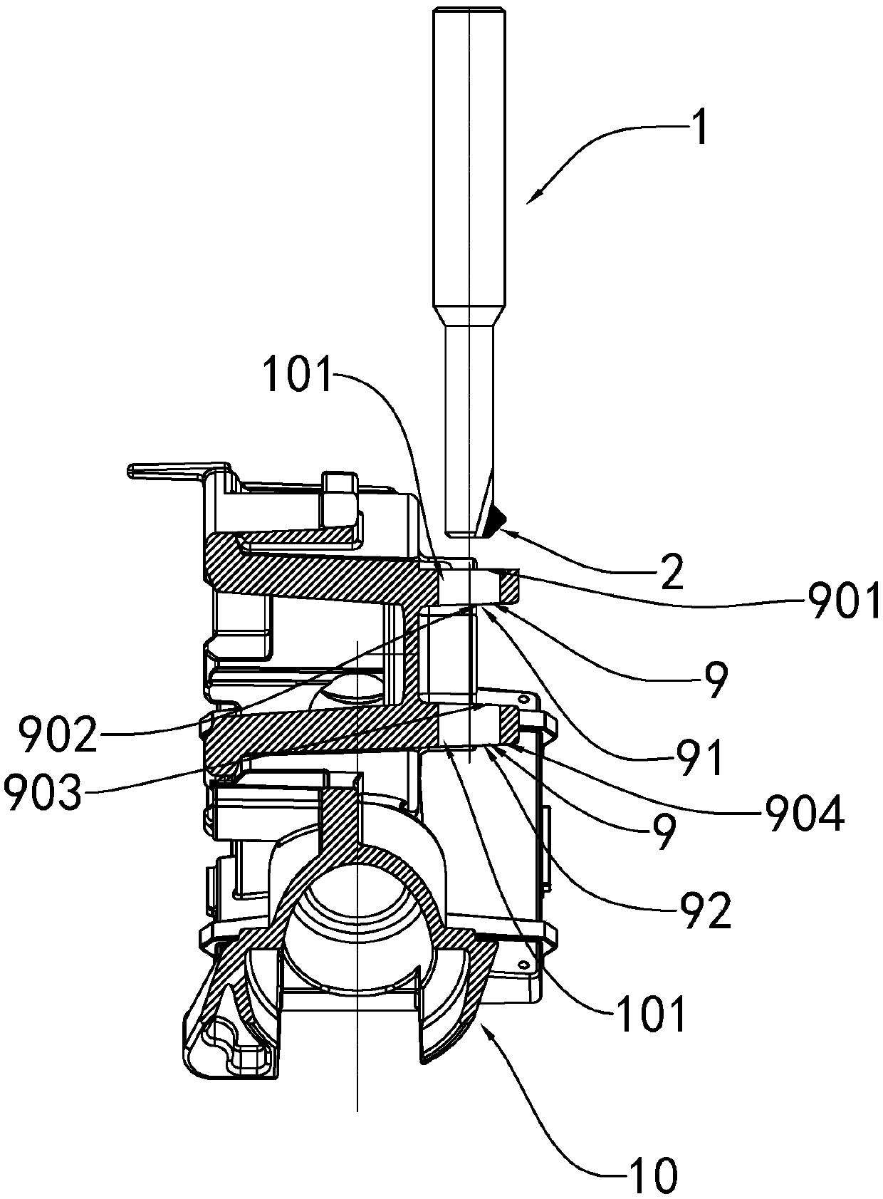
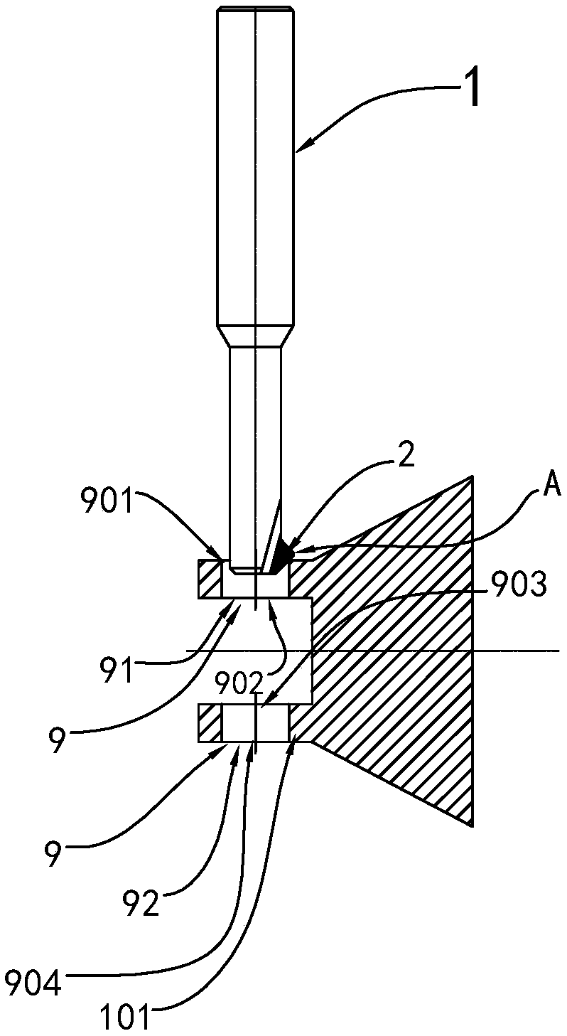
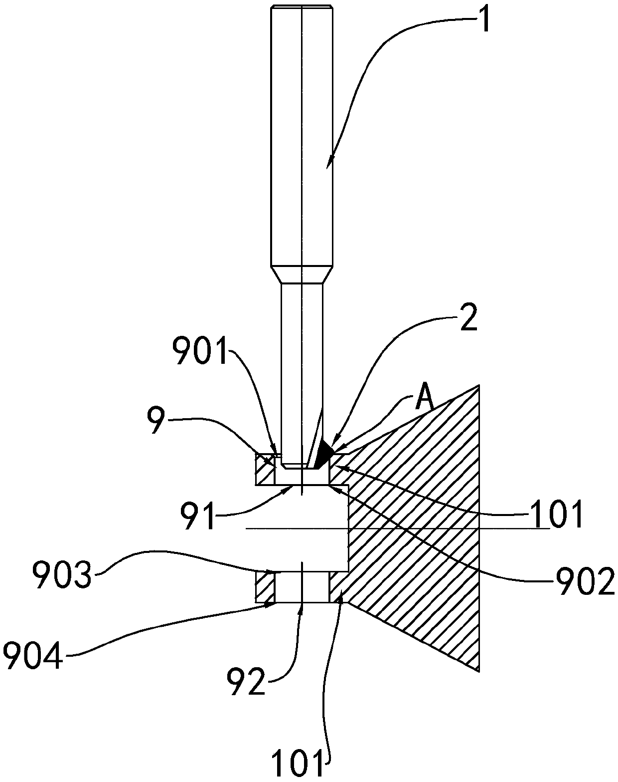
[0039] Such as Figure 1 to Figure 9 As shown, the aluminum die casting processing equipment is used for chamfering the two sides of the through hole 9 of the aluminum die casting 10. For processing the front edge 21 of the front chamfer of the through hole 9 of the aluminum die casting 10 and the reverse blade 22 of the reverse chamfer of the through hole 9 of the aluminum die casting 10, the distance from the center line of the rotating shaft 1 to the farthest end A of the blade portion 2 The distance is greater than the radius of the throu...


PUM


Abstract

The invention discloses an aluminum die casting machining device and method and an aluminum die casting. A rotating shaft is included, a blade part is arranged on one side of the front end of the rotating shaft, and comprises a positive blade used for machining a through hole front face chamfer of the aluminum die casting and a reverse blade used for machining a through hole reverse chamfer of thealuminum die casting, the distance between the center line of the rotating shaft and the farthest end of the blade part is larger than the radius of a through hole to be machined, and the sum of thedistance between the radius of the rotating shaft and the farthest end of the blade part and the distance between the center line of the rotating shaft and the farthest end of the blade part is smaller than the diameter of the through hole. The method comprises the steps that the center of the rotating shaft and the center of the through hole coincide, the rotating shaft rotates, and the positiveblade carries out chamfering the edge of the front face of the through hole; secondly, after the front face of the through hole is chamfered, the rotating shaft stops rotation, the rotating shaft horizontally moves to deviate from the centre of the rotating shaft by a certain distance, the rotating shaft moves downwards by a segment of distance, and the head of the rotating shaft penetrates through the through hole; and thirdly, the rotation of the rotating shaft is started, the reverse blade carries out chamfering on the reverse face edge of the through hole, and the front and reverse face chamfering treatment of the through hole in the aluminum die casting can be finished.

Description

technical field [0001] The invention relates to the field of processing aluminum die-casting parts such as automobile gearbox housings and wiper skeletons, and in particular to processing equipment and processing methods for aluminum die-casting parts such as automobile gearbox casings and wiper skeletons, and the obtained aluminum die-casting products. Background technique [0002] Automobile gearbox housings, wiper skeletons, etc. are all parts of automobiles. The above-mentioned parts use sand molds or metal molds to pour aluminum or aluminum alloys heated into liquid into the mold cavity, and aluminum parts or aluminum alloys of various shapes and sizes are obtained. Alloy parts are usually called aluminum die castings. [0003] Taking the automobile gearbox housing as an example, the parts need to be spliced ​​with each other or installed and fixed on the automobile frame. Usually, some processing equipment is required to process the above-mentioned aluminum die castin...

Claims


Application Information

Patent Timeline
IPC IPC(8): B23D79/00
CPCB23D79/00
Inventor 蔡晓磊
Owner 宁波爱柯迪精密部件有限公司
Why Eureka
Try Eureka