
Stretching-out rebar prefabricated part forming mold and using method thereof

A technology for forming molds and prefabricated parts, applied in the direction of molds, etc., can solve problems such as poor structural strength, short service life, and complicated processes

Inactive Publication Date: 2019-03-26
GUANGDONG LIANCHENG RESIDENTIAL EQUIP INFORMATION TECH CO LTD
View PDF6 Cites 1 Cited by
  • Summary
  • Abstract
  • Description
  • Claims
  • Application Information

AI Technical Summary

Problems solved by technology

This type of traditional mold has more or less design defects, or only considers the rigidity of the mold to ensure the overall structural strength of the mold, but leads to complex production of prefabricated components and mold assembly processes, making it difficult to use on site; or only The production of prefabricated components and mold assembly process are optimized, but part of the rigidity of the mold is sacrificed, resulting in poor structural strength and short service life

Method used


Image

  • Stretching-out rebar prefabricated part forming mold and using method thereof
  • Stretching-out rebar prefabricated part forming mold and using method thereof
  • Stretching-out rebar prefabricated part forming mold and using method thereof

Examples


Embodiment Construction

[0041] In order to make the object, technical solution and advantages of the present invention clearer, the present invention will be further described in detail below in conjunction with the accompanying drawings and specific implementation methods. It should be understood that the specific embodiments described here are only used to explain the present invention, and do not limit the protection scope of the present invention.

[0042] It should be noted that when an element is referred to as being “fixed on”, “disposed on” or “installed on” another element, it may be directly on another element or there may be an intervening element. When an element is considered to be "connected" to another element, it may be directly connected to the other element or there may be an intervening element at the same time; the specific way in which an element is fixedly connected to another element may be achieved through existing technologies, and will not be discussed here. To repeat it aga...


PUM


Abstract

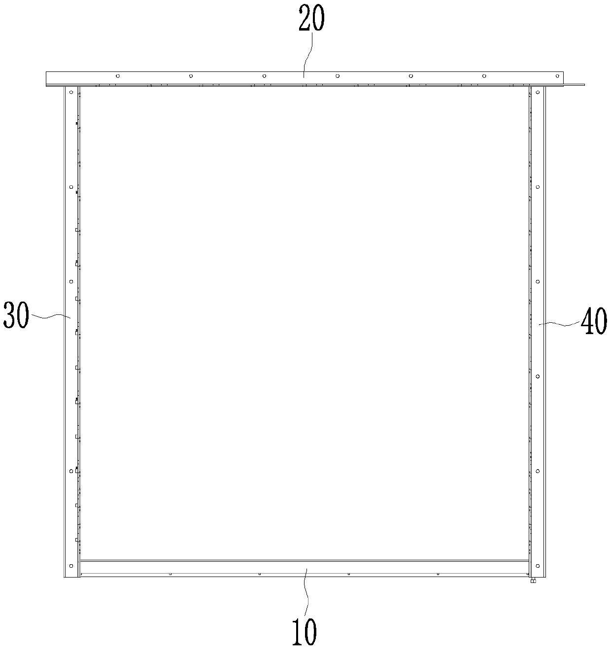
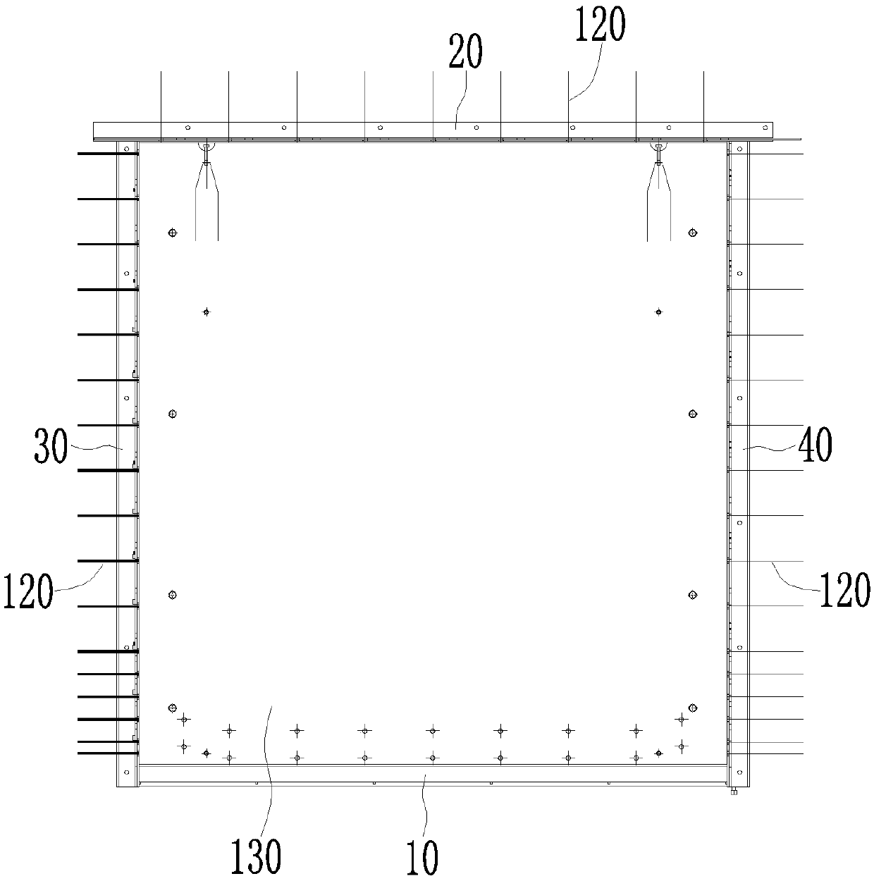
The invention discloses a stretching-out rebar prefabricated part forming mold and a using method thereof. The stretching-out rebar prefabricated part forming mold comprises a bottom side mold, a topside mold, a left side mold and a right side mold, wherein the top side mold and the bottom side mold are oppositely arranged in an spaced mode; the left side mold and the right side mold are oppositely arranged in an spaced mode; one end of the bottom side mold is detachably connected with the left side mold through fasteners, and the other end of the bottom side mold is detachably connected withthe right side mold through fasteners; the end, away from the bottom side mold, of the left side mold is detachably connected with one side of the top side mold through fasteners; and the end, away from the bottom side mold, of the right side mold is detachably connected with one side of the top side mold through fasteners. The connection structure can ensure the high overall structural strengthand rigidity of the mold, meanwhile, the assembling technology is simple and easy to implement, during mold disassembling, the fasteners can be freely unscrewed as required, the corresponding side mold can be dismantled conveniently, the situation that a traditional mold needs to be disassembled in a certain disassembling-assembling sequence is avoided, the flexibility is higher, the operability is high, and the production efficiency is advantageously improved.

Description

technical field [0001] The invention relates to the technical field of moulds, in particular to a mold for forming prefabricated parts with ribs and a method for using the same. Background technique [0002] At present, there are many kinds of molds for casting and forming of prefabricated components on the market, most of which are assembled by several side molds. This type of traditional mold has more or less design defects, or only considers the rigidity of the mold to ensure the overall structural strength of the mold, but leads to complex production of prefabricated components and mold assembly processes, making it difficult to use on site; or only The prefabricated component production and mold assembly process are optimized, but part of the rigidity of the mold is sacrificed, resulting in poor structural strength and short service life. Contents of the invention [0003] Based on this, it is necessary to provide a mold for forming prefabricated parts with ribs, whi...

Claims


Application Information

Patent Timeline
Patent Type & Authority Applications(China)
IPC IPC(8): B28B7/02
CPCB28B7/02
Inventor 不公告发明人
Owner GUANGDONG LIANCHENG RESIDENTIAL EQUIP INFORMATION TECH CO LTD
Learn More