
Tension adjusting roller for wire cutting machine

A tension adjustment and thread cutting machine technology, applied in thin material handling, transportation and packaging, winding strips, etc., can solve the problems of coil winding breakage, coil looseness, etc., to achieve a simple structure and avoid loose strips. Effect

Inactive Publication Date: 2019-03-26
湖北天昱包装材料股份有限公司
View PDF0 Cites 0 Cited by
  • Summary
  • Abstract
  • Description
  • Claims
  • Application Information

AI Technical Summary

Problems solved by technology

[0004] After the tangent is completed, the material after the tangent needs to be rewound. At present, the rewinding roller is used to rewind directly during the rewinding process. It is easy to cause the reeled coil to be rewound due to the difference in tension during the rewinding process. The material is relatively loose or the coil material breaks during the winding process

Method used


Image

  • Tension adjusting roller for wire cutting machine
  • Tension adjusting roller for wire cutting machine
  • Tension adjusting roller for wire cutting machine

Examples


Embodiment 1

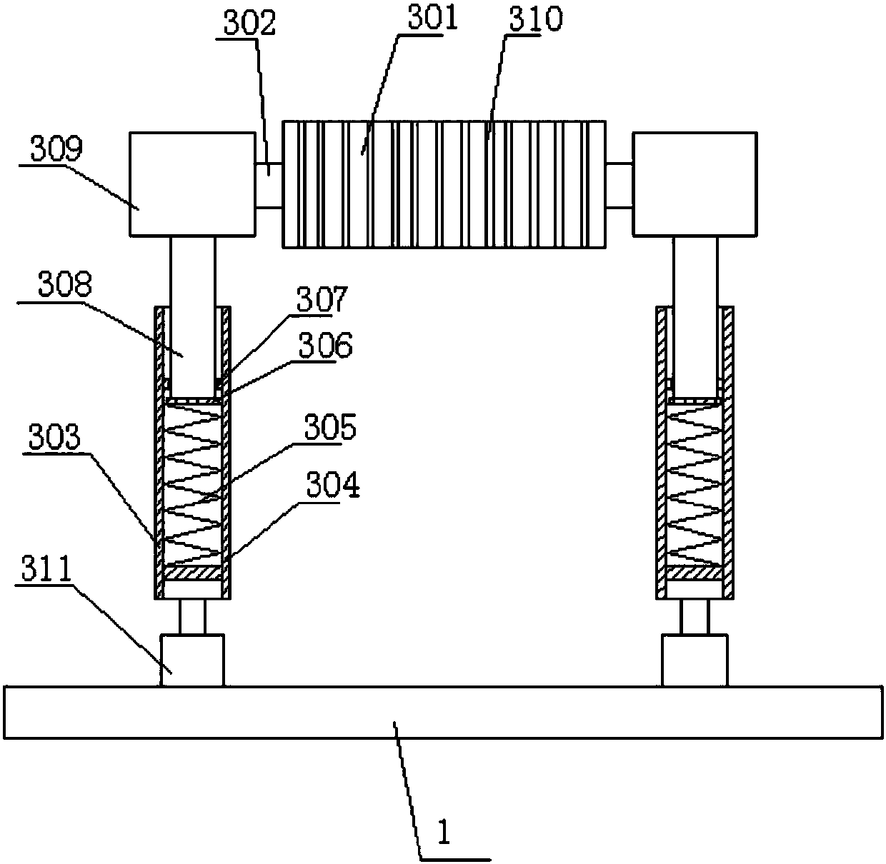
[0027] On the basis of Example 1, such as figure 2 or image 3 The winding tension adjusting roller 3 includes an adjusting roller body 301, a support tube 303 arranged on the base 1 and symmetrical to each other, a support plate 304 is fixed inside the support tube 303, and a stopper is provided above the support plate 304. plate 307, a compression spring 305 is arranged between the baffle plate 307 and the support plate 304, the upper end of the support tube 303 is connected with a support rod 308, and the lower end of the support rod 308 passes through the baffle plate 307 and is located in the compression The compression plate 306 provided on the upper end of the spring 305 is fixedly connected, the upper end of the support rod 308 is provided with a mounting seat 309 , and the adjusting roller rotating shaft 302 provided at both ends of the regulating roller body 301 is connected with the mounting seat 309 . The support plate 304, the baffle plate 307 and the compressio...

Embodiment 2

[0032] On the basis of Example 1, such as figure 2 , Figure 4 and Figure 5 The adjusting roller rotating shaft 302 provided at both ends of the adjusting roller body 301 is fixedly connected with the installation seat 309 .

[0033] The inner rubber layer 314 is set inside the annular wire passing groove 310, and an outer rubber layer 313 is set on the outer cover of the lower rubber layer 314, and multiple A ball 312, the end surface of the ball 312 is exposed through the outer rubber layer 313, and the ball 312 rolls relative to the outer rubber layer 313.

[0034] The balls 312 can roll in the outer rubber layer 313. When the strip is wound in the annular wire groove 310, due to the existence of the balls 313, the strip is on the wound balls to drive the balls to rotate, which is more effective. Less friction between the roller body and the strip reduces the winding force.

Embodiment 3

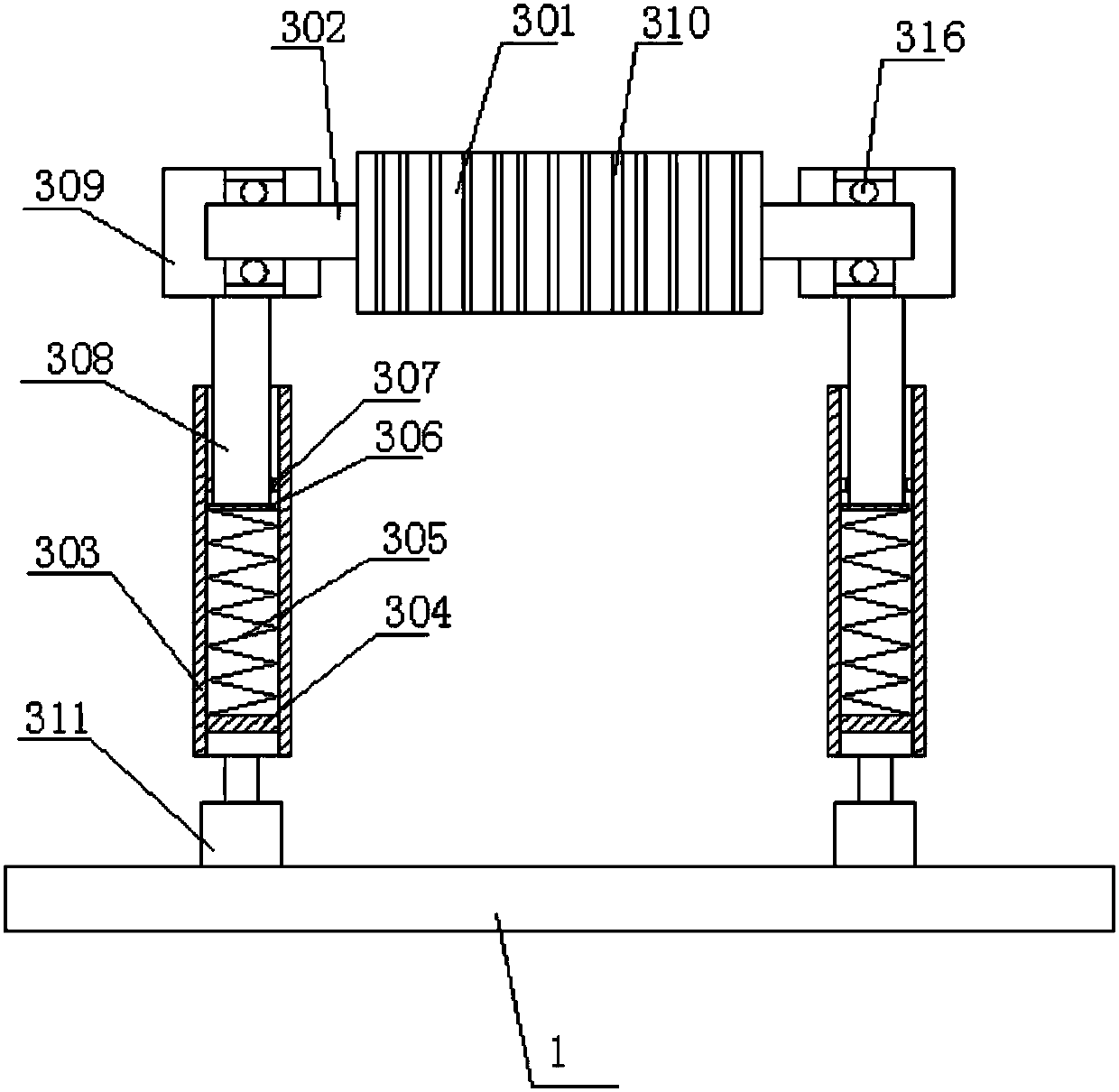
[0036] On the basis of Example 1, as image 3 and Figure 6 The adjusting roller rotating shaft 302 provided at both ends of the adjusting roller body 301 is connected with the mounting seat 309 through a bearing 316 . Using the bearing 316 for connection can effectively reduce the friction between the adjusting roller body 301 and the mounting seat 309 during the rotation process.

[0037] Further, in order to prevent static electricity from being generated during differential winding, a rubber pad 315 is sheathed in the annular wire passing groove 310 .


PUM


Abstract

The invention relates to a tension adjusting roller for a wire cutting machine. The tension adjusting roller comprises an adjusting base, an adjusting roller body and supporting pipes arranged on thebase and mutually symmetric; and supporting plates are fixedly arranged in the supporting pipes, baffles are arranged on the upper parts of the supporting plates, compression springs are arranged between the baffles and the supporting plates, the upper ends of the supporting pipes are connected with supporting rods, the lower ends of the supporting rods penetrate through the baffles to be fixedlyconnected with compressing plates arranged at the upper ends of the compression springs, mounting seats are arranged at the upper ends of the supporting rods, and adjusting roller rotating shafts arranged at the two ends of the adjusting roller body are connected with the mounting seat. The structure is simple, the height of the roller body can be adjusted by the tension adjusting roller through the arranged springs, then automatic adjusting is conducted through force applied by a strip material wound around the roller, thus the tension of the strop material is changed, and the defect that inthe winding process, the strip material is broken due to excessively large tension or the coiled strip material loosens due to the excessively small tension is effectively avoided.

Description

technical field [0001] The invention relates to a tension adjusting roller for a thread cutting machine. Background technique [0002] The thread cutting machine is a special equipment used to press and cut various ordinary cardboard, corrugated cardboard, plastic sheet and leather products. It is suitable for printing, packaging and decoration, plastics and other industries. It has compact structure, excellent manufacture, large cutting force and high precision. High, easy to use, safe and reliable operation and so on. [0003] When the thread cutting machine is working, the controller controls the motor to work, the motor drives the clutch to work, and the clutch controls the deceleration mechanism to work. When the clutch is in the state, the deceleration mechanism works, the crank gear rotates, and the crank gear drives the pressure plate to move through the connecting rod. Driven by the crank gear and connecting rod, the pressure plate reciprocates, adjust the control ...

Claims


Application Information

Patent Timeline
IPC IPC(8): B65H23/26
CPCB65H23/26B65H2404/17B65H2404/1141B65H2402/54
Inventor 丁立兵
Owner 湖北天昱包装材料股份有限公司
Features
  • Generate Ideas
  • Intellectual Property
  • Life Sciences
  • Materials
  • Tech Scout
  • Unparalleled Data Quality
  • Higher Quality Content
  • 60% Fewer Hallucinations
Learn More