
Spinning spindle directly driven by motor for spinning frame

A technology for spinning spindles and spinning frames, which is used in continuous winding spinning machines, spinning machines, textiles and paper making, etc., and can solve problems such as motor bearing damage

Pending Publication Date: 2019-03-26
李廷荔
View PDF11 Cites 1 Cited by
  • Summary
  • Abstract
  • Description
  • Claims
  • Application Information

AI Technical Summary

Problems solved by technology

[0002] At present, the wire feeding rollers of the ring twisting machine and the two-for-one twisting machine are all mechanically structured or one motor drives multiple rollers through one to two long shafts to complete the wire feeding and twisting; although there are individual manufacturers A single roller is used to drive the rotation through a single motor, but due to the vibration of the spindle when the motor rotates at high speed, the spindle is limited by the speed when spinning certain yarns. Downforce, the motor bearings will be damaged

Method used


Image

  • Spinning spindle directly driven by motor for spinning frame
  • Spinning spindle directly driven by motor for spinning frame
  • Spinning spindle directly driven by motor for spinning frame

Examples


Embodiment Construction

[0014] It should be noted that, in the case of no conflict, the embodiments in the present application and the features in the embodiments can be combined with each other. The present invention will be described in detail below with reference to the accompanying drawings and examples.

[0015] In order to enable those skilled in the art to better understand the solution of the present application, the technical solution in the embodiment of the application will be clearly and completely described below in conjunction with the accompanying drawings in the embodiment of the application. Obviously, the described embodiment is only It is an embodiment of a part of the application, but not all of the embodiments. Based on the embodiments in this application, all other embodiments obtained by persons of ordinary skill in the art without creative efforts shall fall within the scope of protection of this application.

[0016] A spinning spindle directly driven by an electric motor, c...


PUM


Abstract

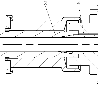
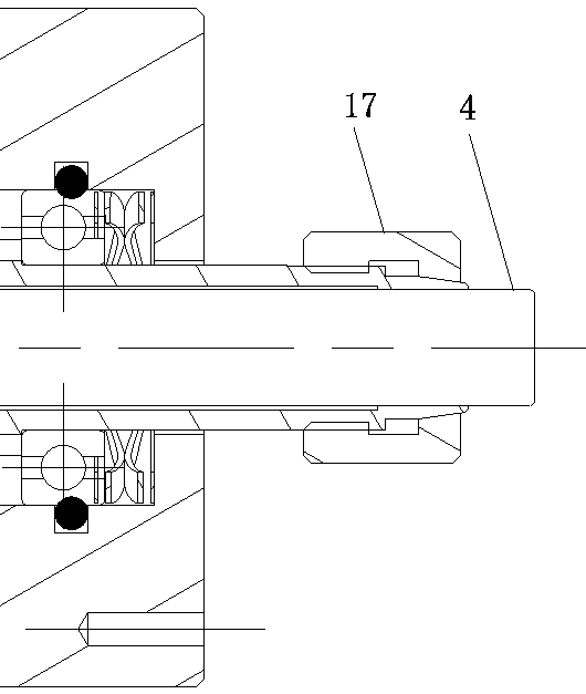
The invention relates to a spinning spindle directly driven by a motor for a spinning frame. The spindle is composed of an aluminum sleeve tube spindle shaft disc combining member, an electric spindlemotor and a conical hole nut, the aluminum sleeve tube spindle shaft disc combining member is composed of a spindle shaft and an aluminum sleeve tube, wherein the spindle shaft is fixedly arranged onthe aluminum sleeve tube. The aluminum sleeve tube spindle shaft disc combining member is connected with the electric spindle motor, and the conical hole nut is arranged on a motor shaft tail of theelectric spindle motor. The cooperative designing between a motor bearing and a motor end cover is clearance fit, a special O-shaped ring is configured to be a bearing center fixing component, the O-shaped ring is also used for shock absorbing when the motor is rotated at a high speed, multiple layers of corrugated springs are configured in a motor tail bearing cover to be used as a motor rotor axial restoring component, the motor rotor shaft can be moved in the axial direction, and it is ensured that the motor shaft is not accidentally damaged when collective doffing is conducted.

Description

technical field [0001] The invention belongs to the field of spinning frames, in particular to a spinning spindle directly driven by a motor. Background technique [0002] At present, the wire feeding rollers of the ring twisting machine and the two-for-one twisting machine are all mechanically structured or one motor drives multiple rollers through one to two long shafts to complete the wire feeding and twisting; although there are some existing manufacturers A single roller is used to drive the rotation through a single motor, but due to the vibration of the spindle when the motor rotates at high speed, the spindle is limited by the speed when spinning certain yarns. Downforce, the motor bearings will be damaged. Contents of the invention [0003] The object of the present invention is to provide a small motor structure for driving a spinning spindle. The invention relates to a spinning spindle directly driven by a motor. The spindle is connected with the motor as a wh...

Claims


Application Information

Patent Timeline
Patent Type & Authority Applications(China)
IPC IPC(8): D01H7/04D01H1/244
CPCD01H1/244D01H7/04
Inventor 李廷荔
Owner 李廷荔
Learn More