
Steel rail noise reduction damper and making and mounting method and vibration absorbing and noise reduction method

A technology of vibration reduction and noise reduction, damper, applied in the direction of track, road, building, etc., can solve the problems of rail vibration and radiation noise to be substantially improved, increase sleeper noise, noise increase, etc.

Active Publication Date: 2019-03-26
ZHUZHOU TIMES NEW MATERIALS TECH
View PDF8 Cites 19 Cited by
  • Summary
  • Abstract
  • Description
  • Claims
  • Application Information

AI Technical Summary

Problems solved by technology

At present, under-rail vibration isolation measures are becoming more and more mature, and the vibration transmitted from the track to the ground foundation can be greatly reduced, but the rail vibration and radiated noise caused by track irregularities have not been substantially improved.
The low-rigidity under-rail backing plate increases the distance that the rail vibration propagates along the rail, so the noise generated by the rail will increase; while the use of a higher-rigidity under-rail backing plate can reduce the noise of the rail, but it will also increase the noise of the sleeper. noise

Method used


Image

  • Steel rail noise reduction damper and making and mounting method and vibration absorbing and noise reduction method
  • Steel rail noise reduction damper and making and mounting method and vibration absorbing and noise reduction method
  • Steel rail noise reduction damper and making and mounting method and vibration absorbing and noise reduction method

Examples


Embodiment Construction

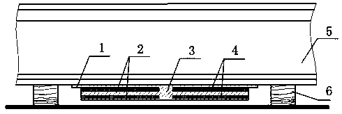
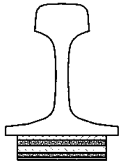
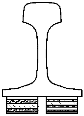
[0063] Please refer to Figure 1 to Figure 6 , a rail noise reduction damper, comprising a mounting plate 1, a resonant plate 2, a connecting body 3 and an elastic damping layer 4. The left and right sides of the connecting body are connected with a mounting plate and a resonance plate, one end of the mounting plate is connected to the top of the side of the connecting body, the resonance plate is located directly below the mounting plate, and one end of the resonance plate is connected to the side of the connecting body; the resonance plate An elastic damping layer is filled between the mounting plate and the mounting plate. Both the mounting plate and the resonance plate are arranged horizontally or roughly horizontally, and the other ends of the mounting plate and the resonance plate are suspended to form a cantilever beam structure; the other ends of the mounting plate protrude from the other end of the resonance plate; the left side of the connecting body and The mountin...


PUM


Abstract

The invention discloses a steel rail noise reduction damper and a making and mounting method thereof and a vibration absorbing and noise reduction method thereof. The steel rail noise reduction dampercomprises resonance plates, elastic damping layers, a connecting body and a mounting plate; one ends of the mounting plate and the resonance plates are connected to the side surface of the connectingbody; and the elastic damping layers are filled between the resonance plates and the mounting plate and between the two adjacent layers of resonance plates. The other ends of the mounting plate and the resonance plates are all impending to form cantilever beam structures. As the damper is connected to a steel rail, each mass layer / restriction layer of the damper is rigidly connected and elastically connected; through rigid connection, the vibration of the steel rail is rapidly transmitted and transferred to each restriction layer of the damper so that the damper can generate resonance deformation, and therefore, the vibration of the steel rail is absorbed, and the noise of the steel rail is reduced. According to the steel rail noise reduction damper, a better vibration absorbing and noisereduction effect can be realized, a safer and more reliable mounting mode is realized, the dampers with different performance parameters can be mixed and used in a matched manner according to needs,the resonance frequency number can be further increased, and the vibration absorbing and noise reduction frequency band can be expanded.

Description

technical field [0001] The invention relates to the technical field of rail transit rail vibration and noise reduction. Background technique [0002] For rail traffic with a speed below 250km / h, wheel-rail noise accounts for the main part of rail traffic noise, and wheel-rail noise is mainly composed of rolling noise, impact noise and squealing noise. Using elastic wheels or wheel noise reduction and damping shock absorbers, squealing noise and wheel radiation noise can be basically controlled; using ultra-long seamless lines, wheel-rail impact noise is also basically controlled, so rolling noise becomes the main wheel-rail noise Element. Noise and vibration are linearly related in the frequency range of 500~2500Hz, and rail is the main radiator of noise in this range. Therefore, suppressing rail vibration and reducing rail sound radiation play a key role in noise reduction of rail lines. At present, under-rail vibration isolation measures are becoming more and more mature...

Claims


Application Information

Patent Timeline
Patent Type & Authority Applications(China)
IPC IPC(8): E01B19/00
CPCE01B19/00E01B19/003
Inventor 查国涛胡金昌傅荣王心龙贺才春涂奉臣周海军
Owner ZHUZHOU TIMES NEW MATERIALS TECH
Learn More