
Energy-saving control device of air compressor

An energy-saving control and air compressor technology, applied in pump control, mechanical equipment, machine/engine, etc., can solve the problems of slow response speed, inability to remotely monitor on-site equipment, and complex air compressors, and achieve the effect of fast response

Pending Publication Date: 2019-03-26
辉统信息科技(常州)有限公司
View PDF0 Cites 0 Cited by
  • Summary
  • Abstract
  • Description
  • Claims
  • Application Information

AI Technical Summary

Problems solved by technology

[0003] In the existing technology, multiple air compressors are generally used to provide power for the automation equipment. Because the manual control of the air compressor is complicated, the corresponding speed is slow, and the misoperation rate is high, therefore, enterprises are more inclined to air compressors. Centralized control and automatic control of machines
[0004] The existing centralized control and automatic control of air compressors generally adopt traditional electrical control methods, which are realized by electrical components such as manual buttons and relays. Although this control method is relatively reliable, it cannot realize intelligent control of the entire system, such as Real-time collection and monitoring of air compressor status and various indicators; due to the development of electrical control intelligence and networking, traditional electrical control cannot remotely monitor field equipment and send and receive real-time data, which can no longer meet the needs of air compressors. Automated Control Requirements

Method used


Image

  • Energy-saving control device of air compressor

Examples


Embodiment Construction

[0015] The present invention will now be described in further detail in conjunction with the accompanying drawings and preferred embodiments. These drawings are all simplified schematic diagrams, which only illustrate the basic structure of the present invention in a schematic manner, so they only show the configurations related to the present invention.

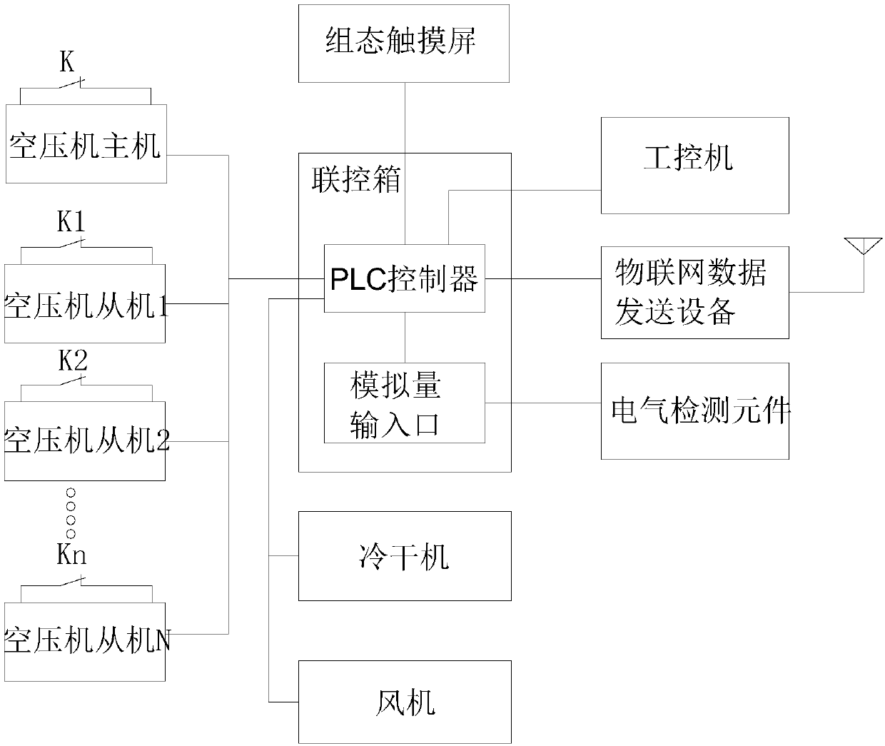
[0016] Such as figure 1 As shown, an air compressor energy-saving control device includes a joint control box, an air compressor master and several air compressor slaves. A configuration touch screen is installed on the joint control box, and a PLC controller is installed inside the joint control box. The main air compressor, the slave air compressor and the configuration touch screen are all electrically connected to the PLC controller, and the PLC controller is also electrically connected to a cold dryer and a fan.

[0017] A number of relays are installed in the joint control box, and the PLC controller controls the main...


PUM


Abstract

The invention relates to an energy-saving control device of an air compressor. The energy-saving control device comprises an air compressor host, a plurality of air compressor slaves and a joint control box. A PLC is disposed in the joint control box; a configured touch screen is mounted on the joint control box; the PLC is connected with the air compressor host, the air compressor slaves and theconfigured touch screen; an air inlet valve of the air compressor host and the air compressor slaves is further provided with an electromagnetic valve which is connected with the PLC; the PLC is connected with an electric detection element through an analog input port; the PLC is connected with Internet of Things data sending equipment through a serial port; the PLC is connected with an industrialpersonal computer through a MODBUS communication interface; and the PLC is further connected with a refrigeration dryer and a fan. By means of the energy-saving control device of the air compressor,the local and remote real-time monitoring of the air compressor can be achieved, and accurate control over the operating states and all indexes of the air compressor can be performed.

Description

technical field [0001] The invention relates to the technical field of industrial automation control, in particular to an energy-saving control device for an air compressor. Background technique [0002] Air compressor is a kind of equipment used to compress air, which is widely used in the field of industrial automation technology to provide power source for various automation equipment. [0003] In the existing technology, multiple air compressors are generally used to provide power for the automation equipment. Because the manual control of the air compressor is complicated, the corresponding speed is slow, and the misoperation rate is high, therefore, enterprises are more inclined to air compressors. Machine centralized control and automatic control. [0004] The existing centralized control and automatic control of air compressors generally adopt traditional electrical control methods, which are realized by electrical components such as manual buttons and relays. Altho...

Claims


Application Information

Patent Timeline
Patent Type & Authority Applications(China)
IPC IPC(8): F04B49/06
CPCF04B49/06
Inventor 许跃华王辉朱旻冯宇晟杨小荣邓军
Owner 辉统信息科技(常州)有限公司
Learn More