
Heat storage type solar heat collection plate installation structure

A technology of solar thermal collectors and installation structures, which is applied in solar thermal collectors, solar thermal energy, mobile/directional solar thermal collectors, etc., and can solve the problems of thermal collectors falling off, difficult to use solar energy, and single structure of thermal collectors , to achieve the effect of good use effect and high light-to-heat conversion rate

Pending Publication Date: 2019-03-26
WUHAN XINBOMING TECH DEV
View PDF0 Cites 0 Cited by
  • Summary
  • Abstract
  • Description
  • Claims
  • Application Information

AI Technical Summary

Problems solved by technology

[0003] The structure of the existing heat storage solar collector plate is relatively simple, and the angle and orientation of the heat collector plate after installation are relatively fixed. It is difficult to maximize the use of solar energy at different times and seasons, and in windy weather, due to the general The solar collector plate is installed at a certain angle, and the airflow blows from the angle direction of the heat collector plate to the heat collector plate, which may easily cause the heat collector plate to fall off, resulting in the fall of the heat collector plate and damage

Method used


Image

  • Heat storage type solar heat collection plate installation structure
  • Heat storage type solar heat collection plate installation structure
  • Heat storage type solar heat collection plate installation structure

Examples


Embodiment Construction

[0021] The following will clearly and completely describe the technical solutions in the embodiments of the present invention with reference to the accompanying drawings in the embodiments of the present invention. Obviously, the described embodiments are only some, not all, embodiments of the present invention. Based on the embodiments of the present invention, all other embodiments obtained by persons of ordinary skill in the art without making creative efforts belong to the protection scope of the present invention.

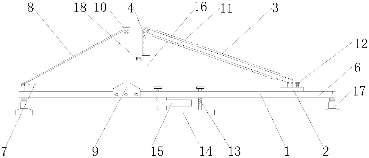
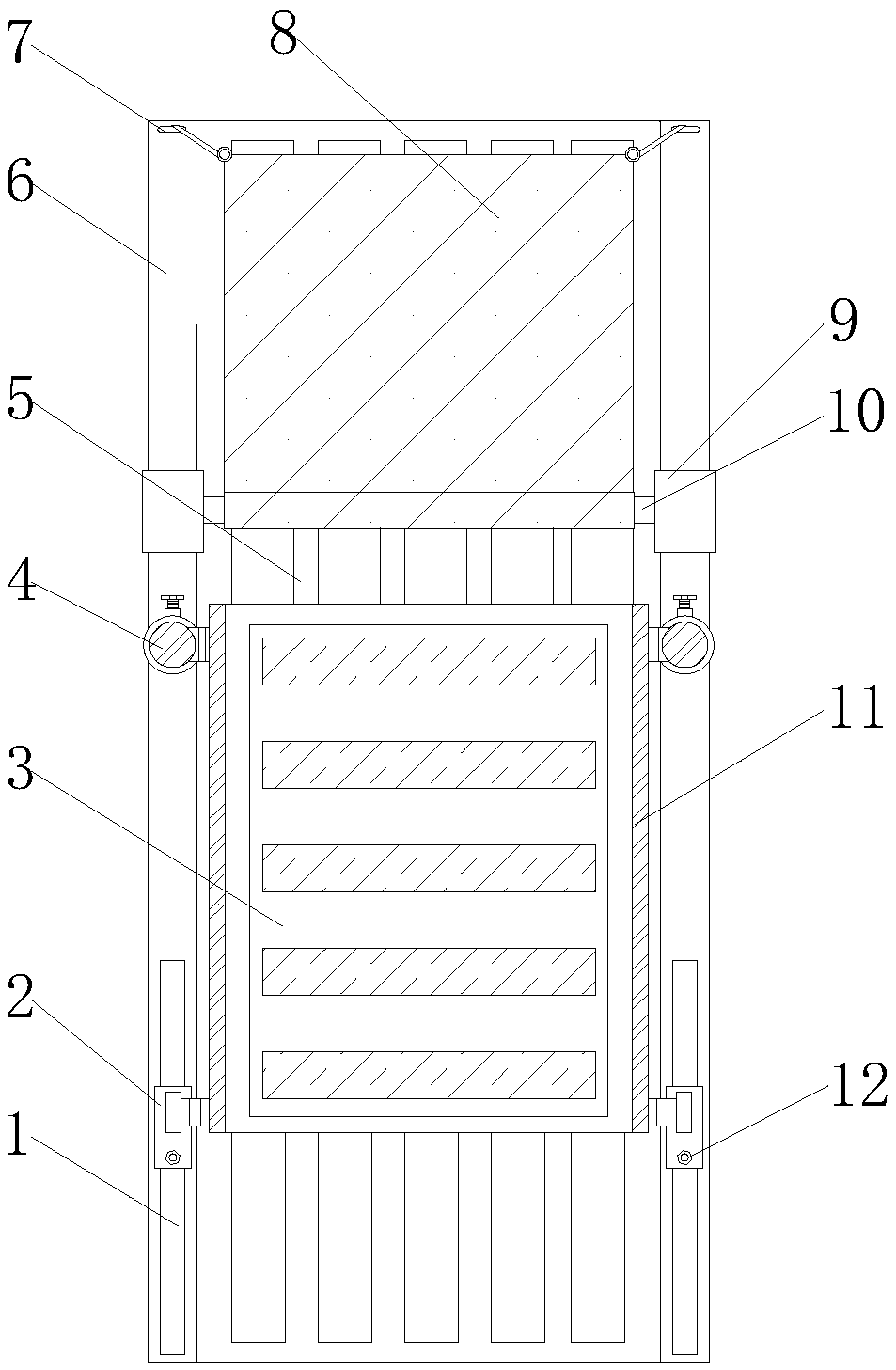
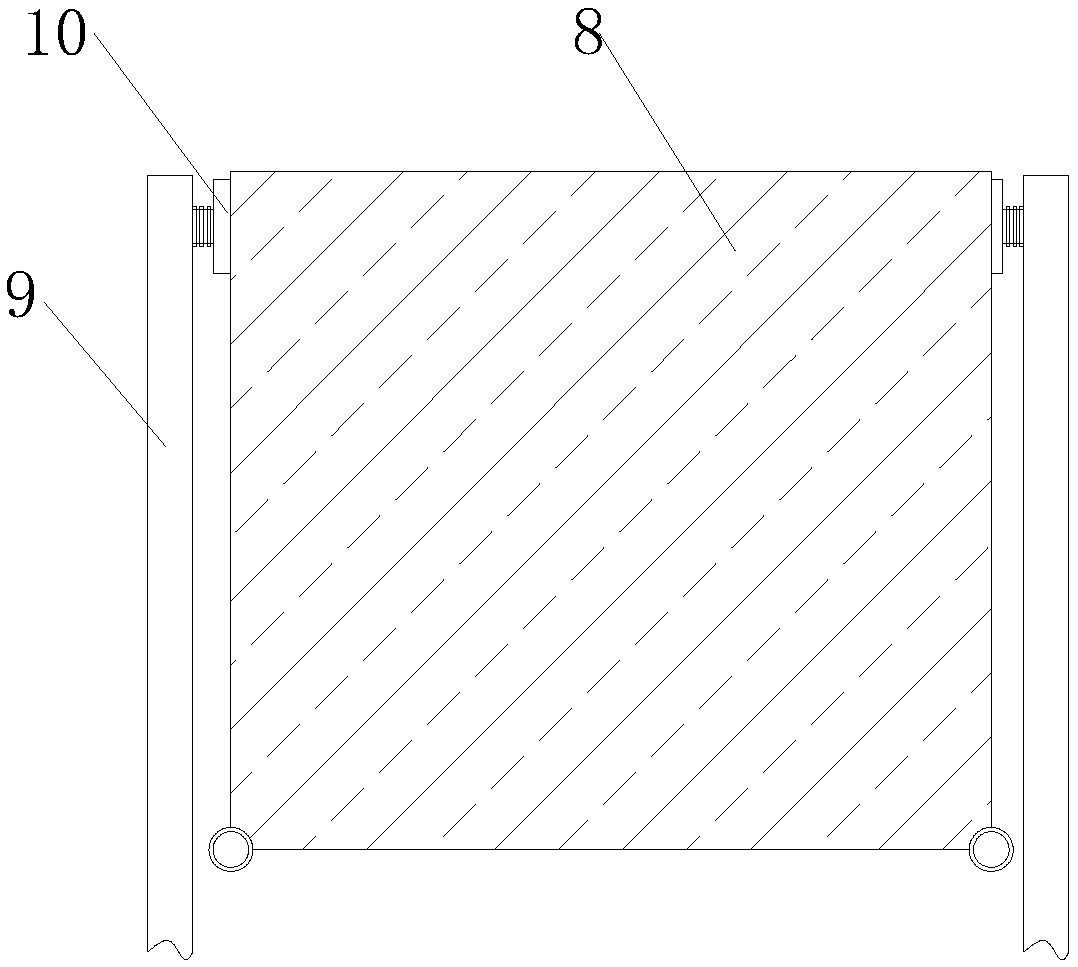
[0022] see Figure 1-3 As shown, an installation structure of a thermal storage type solar collector plate includes a support mechanism, an angle adjustment mechanism, a windshield mechanism and a heat collector plate 3;

[0023] The support mechanism includes fixed angle bolts 13, a seat plate 14, a base plate 5, a rotating shaft 15 and a connecting plate 6, the two sides of the base plate 5 are fixedly connected with connecting plates 6, and the two ends of ...


PUM


Abstract

The invention discloses a heat storage type solar heat collection plate installation structure which comprises a sliding rail, a sliding block, a heat collection plate, a connecting rod, a bottom plate, a connecting plate, a connecting ring, wind retaining shed cloth, a vertical plate, a winding roller, a side plate, a fixed bolt, a constant-angle bolt, a seat plate, a rotary shaft, an adjusting pipe, a support leg and a heightening bolt. The connecting rod and the adjusting pipe are arranged on one side of the bottom end of the solar heat collection plate, and the other side of the bottom endof the solar heat collection plate is slidably connected into a sliding chute in the top end of the connecting plate; through adjusting the length of the connecting rod in the adjusting pipe, the angle of the heat collection plate relative to the ground is adjusted; the seat plate is rotatably connected to the middle of the bottom end of the bottom plate, so that the direction of the whole heat collection plate can be adjusted through rotating the whole seat plate; and through adjusting the angle and the direction, the heat collection plate can conveniently find a better illumination position, so that the photo-thermal conversion rate of the solar heat collection plate is high, and the use effect is good.

Description

technical field [0001] The invention relates to a mounting structure of a heat collecting plate, in particular to a mounting structure of a heat storage type solar heat collecting plate, and belongs to the technical field of application of the mounting structure of a solar heat collecting plate. Background technique [0002] The flat solar collector plate is a device that absorbs solar radiation energy and transfers heat to the working medium. It is a special heat exchanger. The working medium in the heat collecting plate exchanges heat with the distant sun. The board is composed of a heat-absorbing board core, a shell, a transparent cover, heat-insulating materials and related parts. After adding a circulation pipe and a heat-insulating water tank, it becomes able to absorb solar radiation heat and raise the water temperature. [0003] The structure of the existing heat storage solar collector plate is relatively simple, and the angle and orientation of the heat collector p...

Claims


Application Information

Patent Timeline
Patent Type & Authority Applications(China)
IPC IPC(8): F24S10/50F24S30/00F24S30/20F24S30/40
CPCY02E10/44Y02E10/47
Inventor 胡晓利王军
Owner WUHAN XINBOMING TECH DEV
Learn More