Annular micro-channel heat exchanger and fluid flow heat exchange experimental device thereof
A micro-channel heat exchanger and fluid flow technology, which is applied in the direction of modification by conduction heat transfer, cooling/ventilation/heating transformation, electrical components, etc. Low efficiency, unreliable temperature environment of electronic devices, etc., to achieve the effect of improving temperature uniformity, high heat dissipation efficiency, and meeting heat dissipation requirements
- Summary
- Abstract
- Description
- Claims
- Application Information
AI Technical Summary
Problems solved by technology
Method used
Image
Examples
specific Embodiment approach
[0027] It should be noted that the structure, ratio, size, etc. illustrated in the drawings attached to this specification are only used to match the content disclosed in the specification for the understanding and reading of those familiar with this technology, and are not intended to limit the implementation of the present invention. The limitation conditions, any structural modification, proportional relationship change or size adjustment, shall still fall within the scope of the technical content disclosed in the present invention without affecting the effects and objectives that can be achieved by the present invention In the range.
[0028] At the same time, the terms such as "upper", "lower", "left", "right", "middle" and "one" cited in this specification are only for the convenience of description and are not used to limit the text. The scope of implementation of the invention, the change or adjustment of the relative relationship, shall be regarded as the scope of implem...
Embodiment 1
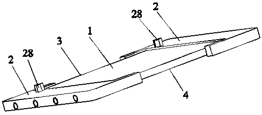
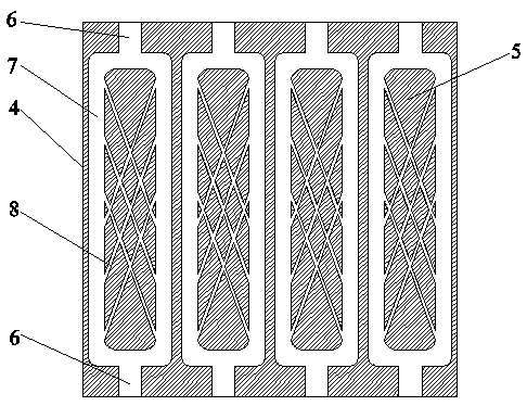
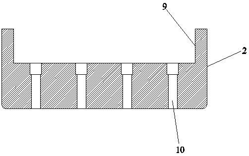
[0030] Such as Figure 1~2 As shown, the present invention discloses a ring-shaped micro-channel heat exchanger, including a substrate 1 and a U-shaped groove 2, wherein there are two U-shaped grooves 2, and the two U-shaped grooves 2 are respectively engaged with the substrate 1 On opposite sides, the base plate 1 includes an upper cover plate 3 and a lower cover plate 4, wherein the lower cover plate 4 is provided with four channels 5, and each channel 5 consists of a primary flow channel 6 and a secondary annular flow channel 7. And the inclined flow channel 8, wherein the primary flow channel 6 of each channel 5 is divided into two parts, and the two primary flow channels 6 are respectively arranged at both ends of the lower cover plate 4. 6 The middle is connected to the secondary annular flow passage 7, wherein the middle area of the secondary annular flow passage 7 is provided with a plurality of inclined flow passages 8. The upper cover plate 3 and the lower cover pla...
Embodiment 2
[0032] Such as Figure 1~2 As shown, the present invention discloses a ring-shaped micro-channel heat exchanger, including a substrate 1 and a U-shaped groove 2, wherein there are two U-shaped grooves 2, and the two U-shaped grooves 2 are respectively engaged with the substrate 1 On opposite sides, the base plate 1 includes an upper cover plate 3 and a lower cover plate 4, wherein the lower cover plate 4 is provided with four channels 5, and each channel 5 consists of a primary flow channel 6 and a secondary annular flow channel 7. And the inclined flow channel 8, wherein the primary flow channel 6 of each channel 5 is divided into two parts, and the two primary flow channels 6 are respectively arranged at both ends of the lower cover plate 4. 6 The middle is connected to the secondary annular flow passage 7, wherein the middle area of the secondary annular flow passage 7 is provided with a plurality of inclined flow passages 8. The upper cover plate 3 and the lower cover pla...
PUM
 Abstract
Description
Claims
Application Information
 - R&D
- Intellectual Property
- Life Sciences
- Materials
- Tech Scout
- Unparalleled Data Quality
- Higher Quality Content
- 60% Fewer Hallucinations
Browse by: Latest US Patents, China's latest patents, Technical Efficacy Thesaurus, Application Domain, Technology Topic, Popular Technical Reports.
© 2025 PatSnap. All rights reserved.Legal|Privacy policy|Modern Slavery Act Transparency Statement|Sitemap|About US| Contact US: help@patsnap.com


