
Glass wiping robot

A glass-cleaning robot and controller technology, applied in robot cleaning machines, cleaning equipment, household appliances, etc., can solve the problems of broken machines, danger, slow speed, etc., and achieve the effect of smooth landing and preventing the machine from falling

Active Publication Date: 2019-03-29
ANHUI POLYTECHNIC UNIV MECHANICAL & ELECTRICAL COLLEGE
View PDF11 Cites 0 Cited by
  • Summary
  • Abstract
  • Description
  • Claims
  • Application Information

AI Technical Summary

Problems solved by technology

[0003] Window (glass) cleaning is one of the cleaning items for every family and every building. However, with the exponential growth of urban high-rise buildings, the area of ​​windows of residents has increased significantly, and the difficulty and danger of cleaning windows have also increased. gave rise to the problem
So far, 95% of the outer glass walls of urban high-rise buildings are cleaned by hand. It is not only expensive, inefficient, and slow, but also extremely dangerous. Incidents of cleaning workers accidentally falling from the building during window cleaning operations continue to occur.
[0004] With the advancement of science and technology, glass-wiping robots (or called glass-wiping equipment, glass-wiping devices) have emerged as the times require. Glass-wiping robots usually have functions such as regular paths, detection of window frames, and automatic cleaning of windows, which can realize cleaning of glass walls. Cleaning or automatic cleaning, the commonly used glass-wiping robots usually need to be adsorbed on the glass during the working process. However, the existing glass-wiping robots are usually not equipped with any fall protection mechanism. In the actual application process, it is easy to have weak adsorption. And the problem of falling from a high altitude and breaking the machine

Method used


Image

  • Glass wiping robot
  • Glass wiping robot
  • Glass wiping robot

Examples


Embodiment 1

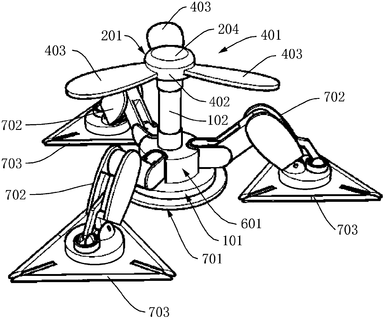
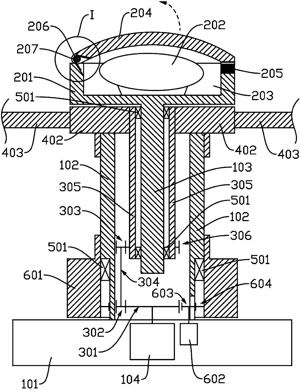
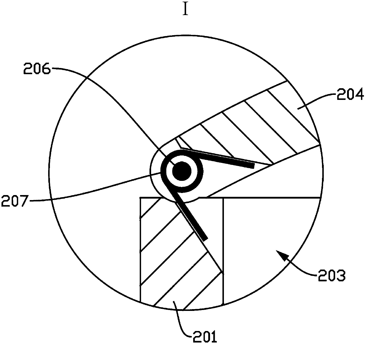
[0031] See figure 1 and figure 2 In this embodiment, a glass-wiping robot is provided, which includes a base 101, a protection chamber 201, a transmission mechanism, and a propeller 401. The base 101 is provided with a cylindrical support tube 102, and the support tube 102 is fixedly arranged inside There is a support column 103. One end of the support column 103 extends out of the support tube 102 and is connected to the protection chamber 201. A parachute 202 is provided in the protection chamber 201; the propeller 401 is sleeved on the support Column 103, the base 101 is provided with a power motor 104, the output shaft of the power motor 104 is connected to the propeller 401 through the transmission mechanism, and the power motor 104 is used to drive the propeller 401 relative to the base 101 and The protection chamber 201 rotates, the propeller 401 is used to carry the base 101 for take-off or landing, and the parachute 202 is used for deceleration and buffering;

[0032] I...


PUM


Abstract

The invention relates to a glass wiping robot. The glass wiping robot is characterized by comprising a base, a protection chamber, a transmission mechanism and a propeller, wherein a supporting cylinder of a cylindrical structure is arranged on the base, a supporting pillar is fixedly arranged in the supporting cylinder, one end of the supporting pillar extends out of the supporting cylinder and is connected with the protection chamber, and a parachute is arranged in the protection chamber; the propeller sleeves the supporting pillar, a power motor is arranged in the base, an output shaft of the power motor is connected with the propeller through the transmission mechanism, the power motor is used for driving the propeller to rotate relative to the base and the protection chamber, the propeller is used for carrying the base to take off or land, and the parachute is used for speed reduction and buffering. The glass wiping robot has a dual protection function, and the situation that therobot falls off can be effectively prevented; meanwhile, under the emergent condition, particularly the condition in which suction is not firm, and the robot falls off from the high altitude, it can be guaranteed that the glass wiping robot can safely and steadily land.

Description

Technical field [0001] The invention relates to the technical field of smart home appliances, in particular to a glass-wiping robot. Background technique [0002] With the development of urban modernization, especially the rise of high-rise buildings, glass construction is not only required for buildings, but also gradually transformed into urban landscapes. Since then, heavy wall cleaning tasks have been derived, and many countries have implemented building wall cleaning requirements. Clearly stipulated. [0003] Window (glass) cleaning is one of the cleaning projects for every family and every building. However, as the number of high-rise buildings in the city doubles, the window area of ​​residents has increased significantly, and the difficulty and danger of cleaning windows has also increased. This gave birth to problems. Up to now, 95% of urban high-rise glass outer walls have been manually cleaned. It is not only expensive, inefficient, and slow, but also extremely dangero...

Claims


Application Information

Patent Timeline
IPC IPC(8): A47L1/02
CPCA47L1/02A47L2201/00
Inventor 王家峻陈国飞王曼
Owner ANHUI POLYTECHNIC UNIV MECHANICAL & ELECTRICAL COLLEGE
Learn More