Shoe washing machine adopting belt drive type shoe washing mechanism

A belt drive and shoe washing machine technology, applied in the field of shoe washing machines, can solve the problems of serious interference, high cost, and restrictions on the development of shoe washing machines, and achieve the effects of reducing power mechanisms and transmission mechanisms, convenient operation, and exquisite structure

Active Publication Date: 2019-03-29
四川鞋唰唰科技有限公司
View PDF5 Cites 4 Cited by
  • Summary
  • Abstract
  • Description
  • Claims
  • Application Information

AI Technical Summary

Problems solved by technology

However, too many power mechanisms and transmission mechanisms lead to serious interference betw

Method used


Image

  • Shoe washing machine adopting belt drive type shoe washing mechanism
  • Shoe washing machine adopting belt drive type shoe washing mechanism
  • Shoe washing machine adopting belt drive type shoe washing mechanism

Examples


Embodiment 1

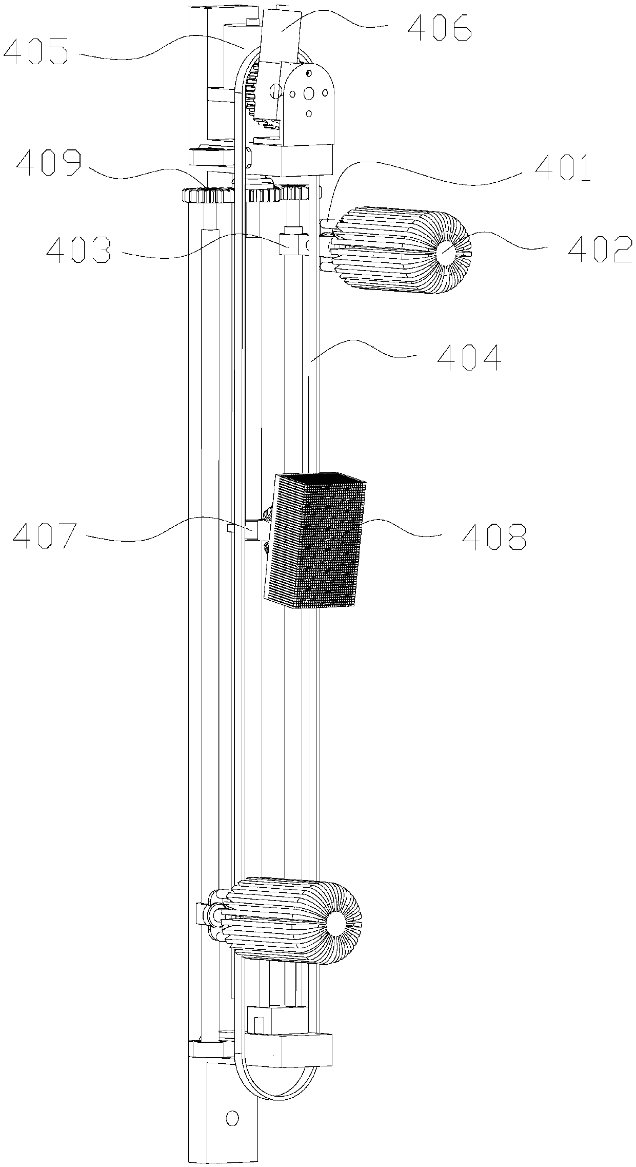
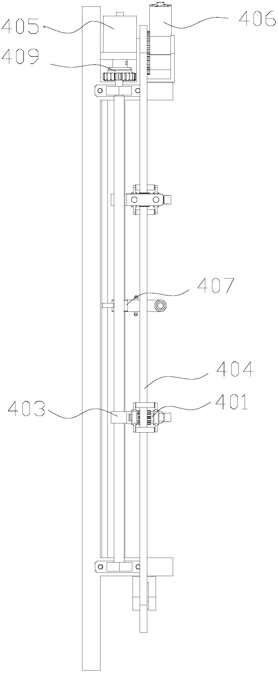
[0035] Such as Figure 1-3 As shown, this embodiment provides a belt-driven shoe washing mechanism, including: a shoe brush mounting base 401 for mounting a shoe brush 402 with a shaft, and the shoe brush 402 with a shaft can rotate on the shoe brush mounting base 401; The screw rod slider mechanism 403, the shoe brush mounting base 401 is installed on the slider of the first screw rod slider mechanism 403, the screw rod of the first screw rod slider mechanism 403 is connected with the first power mechanism 405 in transmission, and the slider is in the Driven by the rotation of the screw rod, it moves along the axial direction of the screw rod; the belt transmission mechanism 404, the synchronous belt of the belt transmission mechanism 404 passes through the shoe brush mounting seat 401, and the synchronous belt is connected with the rotating shaft of the belt shaft shoe brush 402. Specifically, The rotating shaft of the shoe brush with shaft 402 is equipped with a gear adapte...

Embodiment 2

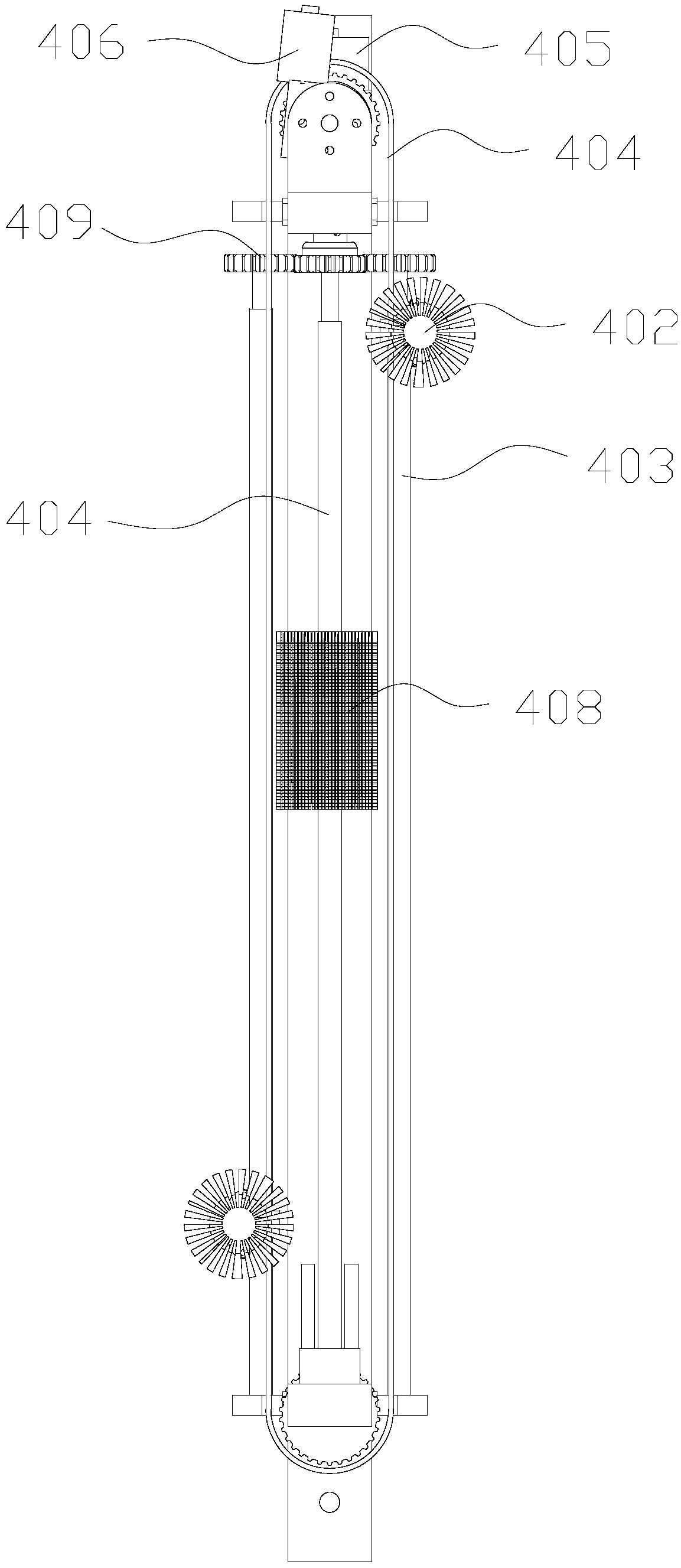
[0040] Such as Figure 4 As shown, this embodiment provides a belt-driven shoe washing mechanism, including: a shoe brush mounting base 401 for mounting a shoe brush 402 with a shaft, and the shoe brush 402 with a shaft can rotate on the shoe brush mounting base 401; The screw rod slider mechanism 403, the shoe brush mounting base 401 is installed on the slider of the first screw rod slider mechanism 403, the screw rod of the first screw rod slider mechanism 403 is connected with the first power mechanism 405 in transmission, and the slider is in the Driven by the rotation of the screw mandrel, it moves along the axial direction of the screw mandrel; the belt transmission mechanism 404, the synchronous belt of the belt transmission mechanism 404 passes through the shoe brush mounting seat 401, and the synchronous belt is connected with the shaft transmission of the belt shaft shoe brush 402, when the belt shaft When the shoe brush 402 and the synchronous belt move relative to ...


PUM


Abstract

The invention discloses a shoe washing machine adopting a belt drive type shoe washing mechanism, and belongs to the technical field of shoe washing devices. The shoe washing machine comprises an outer frame support, an inner frame support, a shoe stretcher support and a belt drive type shoe washing mechanism. The belt drive type shoe washing mechanism is installed on the outer frame support; theshoe stretcher support is installed on the inner frame support; the inner frame support is rotationally connected with the outer frame support through a third power mechanism; the belt drive type shoewashing mechanism comprises a shoe brush installing base, a belt shaft shoe brush, a first lead screw sliding block mechanism and a belt drive mechanism. The belt shaft shoe brush is installed on theshoe brush installing base; the shoe brush installing base is installed on a sliding block of the first lead screw sliding block mechanism, a lead screw of the first lead screw sliding block mechanism is in transmission connection with the first power mechanism; a synchronous belt of the belt drive mechanism penetrates through the shoe brush installing base, and the synchronous belt is in transmission connection with a rotating shaft of the belt shaft shoe brush; the belt drive mechanism is in transmission connection with a second power mechanism. A shoe can be accurately washed, the shoe canalso be subjected to spin-dry operation, and the machine is exquisite in structure and convenient to operate.

Description

technical field [0001] The invention belongs to the technical field of shoe cleaning equipment, and in particular relates to a shoe washing machine adopting a belt-driven shoe washing mechanism. Background technique [0002] Existing shoe washing machines are divided into two types. One is that there is no shoe fixing device. Shoes move randomly in the shoe washing machine and collide with and rub against the shoe brush on the drum to scrub. This kind of shoe washing machine not only easily damages the upper, but also scrubs unevenly, which easily causes local stains to remain. The other is a shoe fixing device. The current shoe fixing device is fixed relative to the shoe washing machine. On the one hand, it is inconvenient to fully clean the upper, and on the other hand, the shoe fixing cannot be dried. [0003] On the other hand, the existing shoe washing machines generally need to design multiple brushes in order to accurately scrub the shoes, and each brush needs to be ...

Claims


Application Information

Patent Timeline
IPC IPC(8): A47L23/02
CPCA47L23/02
Inventor 张魁文志林张文勋
Owner 四川鞋唰唰科技有限公司
Why Eureka
Try Eureka