Parts Forming Equipment

A technology for molding equipment and parts, applied in the field of parts molding equipment, can solve the problems of low efficiency of "ji"-shaped workpieces, achieve the effects of improving connection stability, consistent bending degree, and prolonging service life

Active Publication Date: 2020-04-28
重庆博创知识产权运营有限公司
View PDF6 Cites 0 Cited by
  • Summary
  • Abstract
  • Description
  • Claims
  • Application Information

AI Technical Summary

Problems solved by technology

[0004] The present invention intends to provide parts forming equipment to solve the problem of low efficiency in the prior art of manual bending of "ji"-shaped workpieces

Method used


Image

  • Parts Forming Equipment
  • Parts Forming Equipment

Examples


Embodiment Construction

[0022] The following is further described in detail through specific implementation methods:

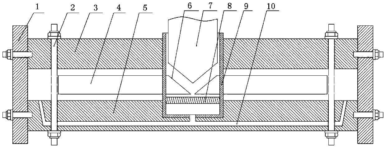
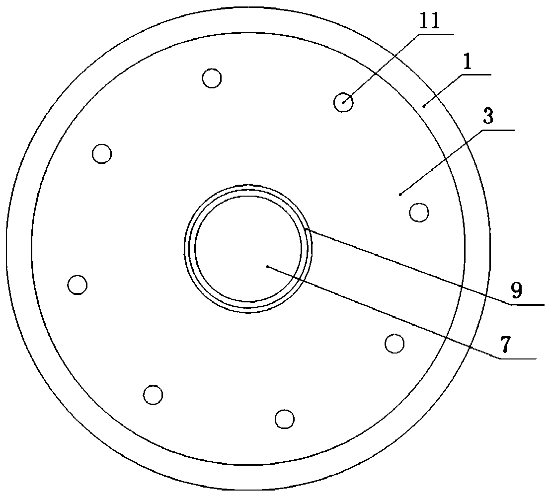
[0023] The reference numerals in the accompanying drawings include: fixed cylinder 1, workpiece 2, top plate 3, stamping rod 4, bottom plate 5, slope 6, driving rod 7, piston 8, conduit 9, air blowing channel 10, upper fixing hole 11.

[0024] Such as figure 1 and figure 2 As shown, the parts forming equipment of the present invention includes a circular top plate 3, on which a number of upper fixing holes 11 are opened, and the upper fixing holes 11 are arranged in a circular array centered on the center of the top plate 3. Bottom plate 5 is installed below top plate 3, and bottom plate 5 is also circular, and bottom plate 5 is provided with some lower fixing holes, and upper fixing hole 11 and lower fixing hole are vertically aligned, and upper fixing hole 11 and lower fixing hole are used for Insert artifact 2. The top plate 3 and the bottom plate 5 are provided with a fixed t...


PUM


Abstract

The invention relates to the electromechanical technical field, in particular to a part forming device. The part forming device comprises a top plate, multiple upper fixed holes are formed in the topplate in an annular array manner, a bottom plate is arranged below the top plate, multiple lower fixed holes are formed in the bottom plate, the upper fixed holes and the lower fixed holes are alignedin the vertical direction, and a stamping mechanism used for stamping a workpiece is arranged between the top plate and the bottom plate. The problem that in the prior art, the efficiency for manually bending n-shaped workpieces is poor is solved.

Description

technical field [0001] The invention relates to the field of electromechanical technology, in particular to parts forming equipment. Background technique [0002] In the field of electromechanical technology, "Ji"-shaped workpieces are usually used. For large "Ji"-shaped workpieces, they are usually directly stamped by large punching machines. However, the small "several"-shaped workpieces used for connection cannot be punched by a punching machine, and are usually manually bent. [0003] In the prior art, workpieces such as small "J"-shaped connectors are bent by workers using tools such as pliers compared with standard parts, which requires a large amount of labor and low efficiency. And during the bending process, in order to ensure the degree of bending of the workpiece, workers also need to compare the workpiece with the standard part at all times, so as to adjust the workpiece. The entire adjustment process is judged by the experience of the workers, which cannot gua...

Claims


Application Information

Patent Timeline
Patent Type & Authority Patents(China)
IPC IPC(8): B21D11/00B21D11/22
CPCB21D11/00B21D11/22
Inventor 王显峰
Owner 重庆博创知识产权运营有限公司
Why Eureka
Try Eureka