Headrest rod stamping die

A technology for stamping die and headrest rod, which is applied in the field of molds for rolling adjustment grooves on headrest rods, can solve the problems of complex processing process and low precision of opening grooves.

Active Publication Date: 2015-07-08
上海兴韬五金有限公司 +2
View PDF8 Cites 9 Cited by
  • Summary
  • Abstract
  • Description
  • Claims
  • Application Information

AI Technical Summary

Problems solved by technology

[0003] At present, the rolling process of the headrest rod adjustment groove usually adopts the rolling process of the headrest rod opening groove. The number of rollers in the groove and the height difference between adjacent rollers lead to low accuracy of the opening groove; Chinese patent CN203437488U also discloses a device f

Method used


Image

  • Headrest rod stamping die
  • Headrest rod stamping die
  • Headrest rod stamping die

Examples


Embodiment Construction

[0024] In order to better understand the headrest rod processing mold of the present invention, a specific embodiment of the present invention will be described in detail below in conjunction with the accompanying drawings and actual working conditions.

[0025] Figure 1a It is a schematic diagram of the structure of the headrest rod before molding, Figure 1b It is a schematic diagram of the structure of the headrest rod after forming. The headrest rod stamping die of the present invention is to realize the headrest rod workpiece by Figures 1a to 1b processing. The specific shape and number of the grooves on the headrest rod are determined by the actual requirements. It can be formed as the groove shown in the figure, or formed into grooves of other suitable shapes.

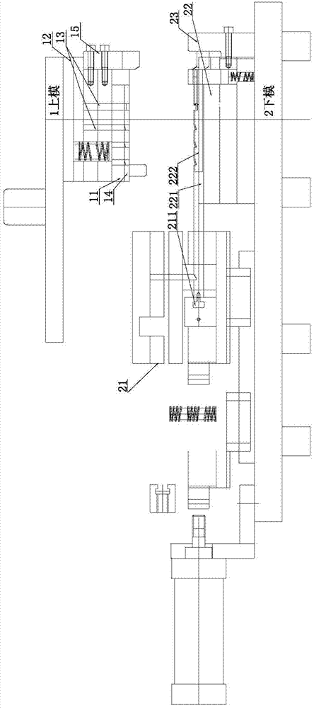
[0026] Such as Figure 2 to Figure 3 As shown, the headrest bar stamping die of the present invention includes an upper mold 1 and a lower mold 2, and the upper mold 1 includes a stripping plate 11, a stampi...


PUM


Abstract

The invention provides a headrest rod stamping die. The headrest rod stamping die comprises an upper die (1) and a bottom die (2), wherein the lower die (2) comprises a left movable module (21) and a right movable module (22); a positioning hole (211) conforming to the shape of a headrest rod workpiece is formed in the left movable module (21); a lower half groove (221) coaxial with the positioning hole (211) of the left movable module (21) and conforming to the shape of the headrest rod workpiece is formed in the right movable module (22) of the bottom die (2); a core rod assembly is further arranged on the right movable module (22). Compared with the stamping die with both the left movable module and the right movable module in the prior art, the headrest rod stamping die is simple in structure and small in floor area, and furthermore, the manufacturing cost of the die is also reduced and the headrest rod stamping efficiency is improved.

Description

technical field [0001] The invention relates to a mold for manufacturing a headrest rod of an automobile seat, in particular to a mold for rolling an adjusting groove on the headrest rod. Background technique [0002] The headrest rod is an indispensable part of the car seat. The seat headrest is installed on the upper part of the backrest through the headrest rod. The headrest rod is processed with a number of adjustment grooves for adjusting the height of the headrest. The cooperation between the bayonet pin inside and the adjustment groove of the headrest rod can limit the headrest at different heights. [0003] At present, the rolling process of the headrest rod adjustment groove usually adopts the rolling process of the headrest rod opening groove. The number of rollers in the groove and the height difference between adjacent rollers lead to low accuracy of the opening groove; Chinese patent CN203437488U also discloses a device for manufacturing headrest rods, although...

Claims


Application Information

Patent Timeline
IPC IPC(8): B21D37/10B21D22/06
CPCB21D22/06B21D37/10B21D45/006
Inventor 马志兴
Owner 上海兴韬五金有限公司
Why Eureka
Try Eureka