Tool for support assembly on radiator pull rod and using method thereof

A technology of bracket assembly and radiator, applied in the field of tooling of bracket assembly on radiator pull rod, can solve problems such as bracket damage to radiator, bracket deformation, warpage deformation of bracket welding part, etc.

Inactive Publication Date: 2019-03-29
合肥东铭机械制造有限公司
View PDF5 Cites 0 Cited by
  • Summary
  • Abstract
  • Description
  • Claims
  • Application Information

AI Technical Summary

Problems solved by technology

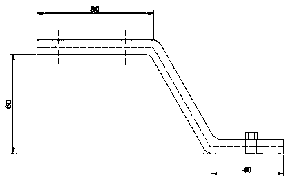
[0002] During automobile manufacturing, especially the radiator on heavy-duty commercial vehicles, the bracket needs to be fixed on the body. Since the bracket itself is in a Z shape, it needs to be bent. It is difficult to keep the angle of the bent part consistent during bending, so a mold is required to bend it. The shape after bending is tested. At the same time, in order to facilitate the fixing of the radiator, a nut needs to be welded on one end of the bracket. However, the bracket itself is simple in structure and small in size and is suitable for mass production. Due to mass production, if the positioning of the nut is not accurate, it is easy to cause the bracket If the radiator is damaged in batches or cannot be fixed well, it will affect the fixing and installation of the radiator on the one hand, and on the other hand, the batch damage to the bracket will increase the production cos...

Method used


Image

  • Tool for support assembly on radiator pull rod and using method thereof
  • Tool for support assembly on radiator pull rod and using method thereof
  • Tool for support assembly on radiator pull rod and using method thereof

Examples


Embodiment Construction

[0020] Embodiments of the present invention are described in detail below, examples of which are shown in the drawings, wherein the same or similar reference numerals designate the same or similar elements or elements having the same or similar functions throughout. The embodiments described below by referring to the figures are exemplary and are intended to explain the present invention and should not be construed as limiting the present invention. In the description of the present invention, it should be understood that the orientation or positional relationship indicated by the terms "upper", "lower", "front", "rear" etc. is based on the orientation or positional relationship shown in the drawings, and is only for It is convenient to describe the present invention and simplify the description, but does not indicate or imply that the device or element referred to must have a specific orientation, be constructed and operate in a specific orientation, and thus should not be con...


PUM


Abstract

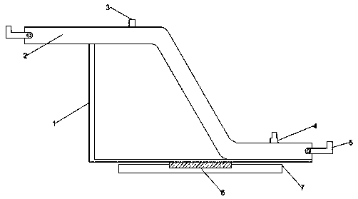
The invention discloses a tool for a support assembly on a radiator pull rod and a using method thereof. The tool comprises a supporting frame, a die and a fixing block, wherein the die is fixedly connected to the upper end of the supporting frame, and the fixing block is fixed at the lower end of the supporting frame; a limiting column and a limiting bulge are arranged on the upper surface of thedie, the two ends of the die are connected to L-shaped fixing blocks through shaft pins, the support assembly on the radiator pull rod is placed on the die, and through holes in the support assemblyon the radiator pull rod are sequentially placed on the limiting column and the limiting bulge; and the L-shaped fixing blocks are rotated, the support assembly on the radiator pull rod is fixed on the upper surface of the die, a nut penetrates through the limiting bulge to be connected to the upper surface of the support assembly on the radiator pull rod, and welding is carried out after connection. According to the tool and the using method, through the arrangement of the device, the welding procedures of the support assembly on the radiator pull rod is greatly simplified, the welding deformation of the support assembly on the radiator pull rod is reduced, due to the limiting bulge, the positioning of the nut is ensured to be accurate, so that the support assembly on the radiator pull rod is convenient to install at the later stage.

Description

technical field [0001] The invention relates to the technical field of automobile brackets, in particular to a tooling used for a bracket assembly on a radiator tie rod and a method for using the same. Background technique [0002] During automobile manufacturing, especially the radiator on heavy-duty commercial vehicles, the bracket needs to be fixed on the body. Since the bracket itself is in a Z shape, it needs to be bent. It is difficult to keep the angle of the bent part consistent during bending, so a mold is required to bend it. The shape after bending is tested. At the same time, in order to facilitate the fixing of the radiator, a nut needs to be welded on one end of the bracket. However, the bracket itself is simple in structure and small in size and is suitable for mass production. Due to mass production, if the positioning of the nut is not accurate, it is easy to cause the bracket If the radiator is damaged in batches or cannot be fixed well, it will affect the ...

Claims


Application Information

Patent Timeline
IPC IPC(8): B23K31/00B23K37/04B23K37/047
CPCB23K31/003B23K37/0443B23K37/047
Inventor 张永寿
Owner 合肥东铭机械制造有限公司
Why Eureka
Try Eureka