Girder machining method and girder machining device for crane and crane span collecting-mounting method

A processing method and processing device technology, applied in the direction of metal processing, metal processing equipment, workbench, etc., can solve the problems of inability to realize modularization, batch production, wheel gnawing rails, long assembly cycle, etc., and achieve easy interchangeability Assembly and modular production, eliminating welding deformation, and ensuring the quality of assembly

Active Publication Date: 2014-01-01
HENAN WEIHUA HEAVY MACHINE
View PDF5 Cites 9 Cited by
  • Summary
  • Abstract
  • Description
  • Claims
  • Application Information

AI Technical Summary

Problems solved by technology

However, due to the need for welding at the end, the deformation caused by welding will have a great impact on the shape of the entire bridge frame, especially on the parameters such as the horizontal and vertical deflection of the cart wheel and t

Method used


Image

  • Girder machining method and girder machining device for crane and crane span collecting-mounting method
  • Girder machining method and girder machining device for crane and crane span collecting-mounting method
  • Girder machining method and girder machining device for crane and crane span collecting-mounting method

Examples


Embodiment Construction

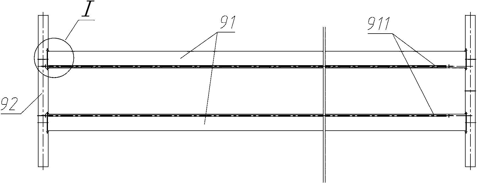
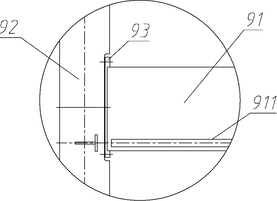
[0036] An embodiment of the crane main beam processing device in the present invention Figure 4~Figure 18 As shown, it includes two support tables 7 arranged side by side at intervals and a mobile boring and milling machine 11 arranged on the outside of the support table 7 in the width direction. Both ends of the main beam 1 in the length direction can be supported on the support tables 7 respectively.

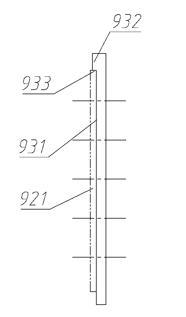
[0037] Each support table 7 includes a bottom support 8, a square box 9 and a fixing device for pressing and fixing the square box 9 to the bottom support 8. The square box 9 is a cuboid-shaped box structure, and the bottom plate of the square box 9 The edges of the two sides extend out of the outer surface of the side plates, the corresponding pressing plate 18 of the fixing device can be laid on the edge, and then the pressing plate 18 is fixed to the bottom support 8 through the corresponding bolts, and the square box 9 can be compressed Fixed on the bottom support 8. The st...


PUM


Abstract

The invention relates to a girder machining method and a girder machining device for a crane and a crane span collecting-mounting method. The girder machining method for the crane comprises the following steps of step 1, welding girder hanging plates onto corresponding positions of two ends in the length direction of the girder, and enabling the side faces of the girder hanging plates to face the outside of the length direction of the girder; step 2, placing a girder bracket onto a corresponding girder support, fixing by a girder fixing device on the girder support, and utilizing corresponding machining equipment to machine a pressing plane used for being pushed and matched with corresponding matching faces on end beams; step 3, machining thread connecting holes penetrating through the girder hanging plates along the thickness direction in set positions of the girder hanging plates; finally, jointing the end beams with the girder and fixing the end beams and the girder by bolts. By adopting the technical scheme, the collecting-mounting quality of a crane span is prevented from being influenced by welding deformation.

Description

Technical field [0001] The invention relates to a crane main beam processing method, a main beam processing device and a bridge assembly method. Background technique [0002] The crane bridge is a main part of the crane. It includes a main beam 91 and an end beam 92 arranged perpendicular to each other. The end beams 92 are fixed at both ends of the main beam 91 in the length direction. Run on the corresponding bridge track. The crane can be divided into single-beam type and double-beam type according to the number of main beams 91 in the bridge. A type of double-beam crane bridge in the prior art such as figure 1 — image 3 As shown, it includes two main beams 91 with a trolley rail 911 on the top and two end beams 92. The extension direction of the trolley rail 911 is consistent with the length direction of the main beam 91. 92 is fixedly connected together by the main beam hanging plate 93. The structure of the main beam hanging plate 93 is as follows image 3 As shown, it i...

Claims


Application Information

Patent Timeline
IPC IPC(8): B23P15/00
CPCB23P15/00B23Q9/0028B23Q37/00B25H1/00B25H7/00
Inventor 史之杰张爱国王跃文高宝龙
Owner HENAN WEIHUA HEAVY MACHINE
Why Eureka
Try Eureka