
Automatic assembling device for assemblies

An automatic assembly device and automatic assembly technology, applied in the direction of assembly machines, metal processing equipment, manufacturing tools, etc., can solve the problem of low economic efficiency

Active Publication Date: 2019-03-29
CHINA NORTH NUCLEAR FUEL +1
View PDF9 Cites 2 Cited by
  • Summary
  • Abstract
  • Description
  • Claims
  • Application Information

AI Technical Summary

Problems solved by technology

[0003] The purpose of the present invention is to provide an automatic assembly device for fast reactor components, to solve the problem of low economic efficiency in the manual assembly of fast reactor nuclear fuel elements at present, and to ensure the assembly accuracy requirements of components

Method used


Image

  • Automatic assembling device for assemblies
  • Automatic assembling device for assemblies

Examples


Embodiment Construction

[0018] The present invention will be described in detail below in conjunction with the accompanying drawings and specific embodiments.

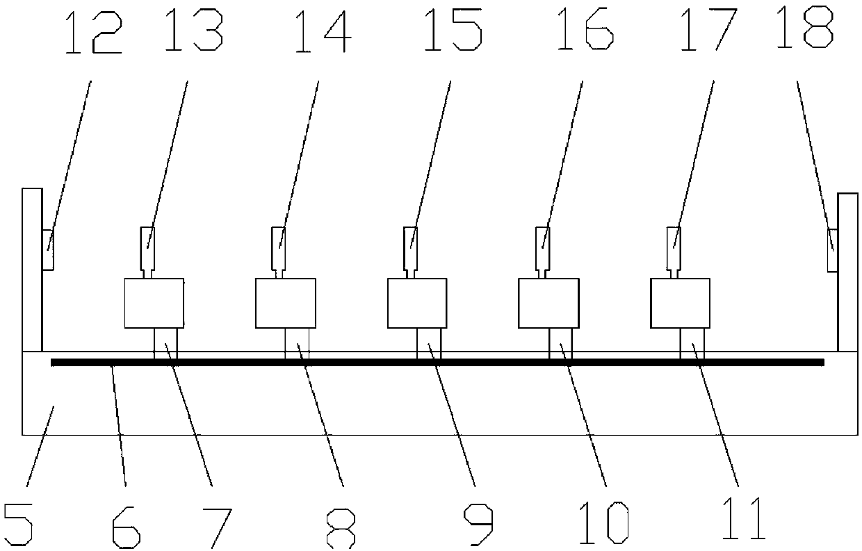
[0019] Component structure see figure 1 , The assembly consists of an upper operating head 1, an outer casing 2, a rod bundle 3, and a lower secondary component 4. The structure of the component automatic assembly device is shown in figure 2 , consisting of equipment bed 5, rack 6, motor a7, motor b8, motor c9, motor d10, motor e11, force sensor a12, jaw a13, jaw b14, jaw c15, jaw d16, jaw e17, The force sensor b18 is composed. The equipment bed 5 is placed horizontally, and the rack 6 whose length is equal to the equipment bed 5 is installed above the equipment bed 5 . Jaw a13 , jaw b14 , jaw c15 , jaw d16 , jaw e17 are connected to rack 6 through motor a7 , motor b8 , motor c9 , motor d10 and motor e11 respectively. The output ends of motor a7, motor b8, motor c9, motor d10, and motor e11 are gears meshing with rack 6, and the motors r...


PUM


Abstract

The invention belongs to the technical field of nuclear fuel element assembly assembling technologies, and particularly relates to an automatic assembling device for assemblies. An equipment lathe body is horizontally arranged, and a rack is installed over the equipment lathe body; clamping claw a, a clamping claw b, a clamping claw c, a clamping claw d and a clamping claw e are connected with therack through a motor a, a motor b, a motor c, a motor d and a motor e respectively, and the motors rotate to drive the clamping claws to horizontally move in the rack direction; and a force sensor aand a force sensor b are installed on the two sides of the equipment lathe body. According to the automatic assembling device for the assemblies, the problem that at present, the economical efficiencyis low when fast reactor nuclear fuel elements are manually assembled is solved, and the assembly assembling precision requirement is guaranteed.

Description

technical field [0001] The invention belongs to the technical field of assembly technology of nuclear fuel element assemblies, and in particular relates to an automatic assembly device for assemblies. Background technique [0002] The structure of fast reactor nuclear fuel elements is quite different from that of PWR nuclear fuel elements, and cannot be assembled with existing PWR nuclear fuel element assembly tools. During the manufacturing process of the mock parts of fast reactor nuclear fuel elements, manual assembly is used for assembly. The assembly has large volume, heavy weight, high assembly precision and other assembly difficulties. The manual assembly method has many personnel and a long assembly cycle, which greatly affects the economy of fast reactor fuel elements. Contents of the invention [0003] The object of the present invention is to provide an automatic assembly device for fast reactor components to solve the problem of low economic efficiency in manu...

Claims


Application Information

Patent Timeline
IPC IPC(8): B23P21/00
CPCB23P21/00
Inventor 布仁刘长城张成云韩志华任永岗李庆杰赵毅朝孙刚峰李刚张鹏举王珅玮宋永刚陈娟林宗奇
Owner CHINA NORTH NUCLEAR FUEL
Learn More