Protection device for ultrasonic image instrument
A protection device, ultrasonic imaging technology, applied in transportation and packaging, vehicles for freight, load fixing, etc., to achieve the effect of simple structure, convenient operation and strong practicability
- Summary
- Abstract
- Description
- Claims
- Application Information
AI Technical Summary
Problems solved by technology
Method used
Image
Examples
Embodiment 1
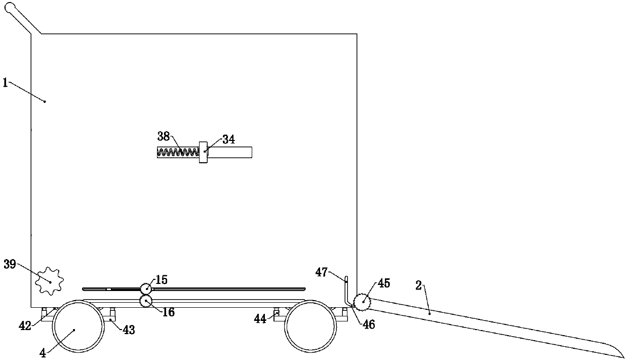
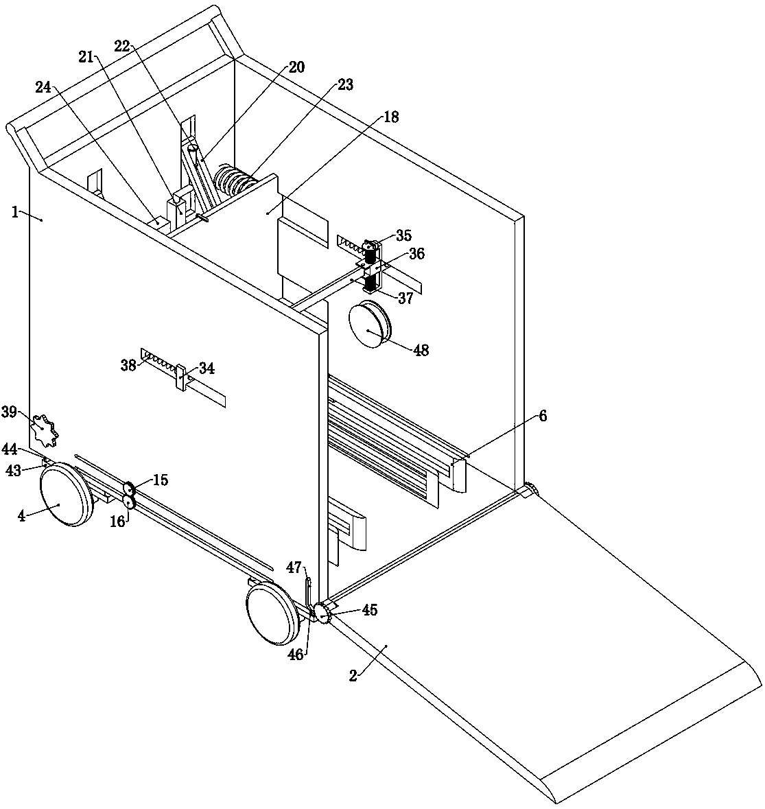
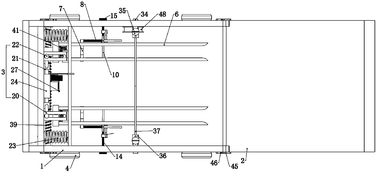
[0032] Embodiment 1, the present invention is a protective device for ultrasonic imaging instruments, which includes a hollow box 1 without a top and an opening on the right side. The box 1 is used to store ultrasonic imaging instruments that need to be transported, and the ultrasonic imaging instruments that need to be transported are placed in the box Inside the body 1, the box body 1 can protect it. At the same time, the box body 1 can also provide a fixed foundation for the subsequent structure. It is characterized in that the right side of the box body 1 is rotatably connected with a door panel 2, The door panel 2 can be lowered when the instrument needs to be pushed into the box body 1, and becomes a slope so that the user can push the instrument into the box body 1. After the instrument is pushed into the box body 1, the user can push the door panel 2 Closed, the front and rear of the box 1 is slidingly connected with a wheel 4 fixing device, and the wheel 4 fixing devic...
Embodiment 2
[0034] Embodiment 2. On the basis of Embodiment 1, this embodiment provides a specific structure of a one-way clamping device to ensure that it can drive the rotating clamping plate when the instrument enters the box 1 and the instrument wheel 4 moves to the left. 10 rotates, but when the instrument wheel 4 moves to the right, it prevents the rotation clamp 10 from rotating, thereby fixing the instrument wheel 4 in the box body 1, thereby fixing the instrument in the box body 1, specifically, the one-way clamp The tightening device includes a one-way clamp 11 fixedly connected to the front wheel clamp 9, and a one-way clamp 12 is connected to the one-way clamp 11 in rotation, and the left side of the one-way clamp 12 is A limit shaft 13 fixedly connected to the one-way card base 11 is provided, and a one-way card plate 12 coil spring is fixedly connected to the rotating shaft of the one-way card base 12 and the one-way card base 11, so that For the reset of one-way card board ...
Embodiment 3
[0035] Embodiment 3, on the basis of Embodiment 2, this embodiment provides a specific structure for adjusting the specific position of the one-way deck 11, so that when the instrument is transported to the destination, the instrument is pushed out of the box 1. The movement of the instrument is not affected by the rotating clamp 10 and its related structures. Specifically, the two one-way decks 11 are all slid back and forth and connected to the corresponding front wheel decks 9. Refer to Figure 4 , two guide shafts are fixedly connected side by side on the described front wheel deck 9, and the one-way deck 11 is sleeved on the two guide shafts to realize sliding back and forth. Meanwhile, the front wheel deck 9 The movement of the one-way deck can also drive the movement of the one-way deck 11, and each of the one-way decks 11 is equipped with a one-way deck screw 14. Specifically, the one-way deck 11 is provided with a single To the threaded hole of the card seat 11, the o...
PUM
 Abstract
Description
Claims
Application Information
 - R&D
- Intellectual Property
- Life Sciences
- Materials
- Tech Scout
- Unparalleled Data Quality
- Higher Quality Content
- 60% Fewer Hallucinations
Browse by: Latest US Patents, China's latest patents, Technical Efficacy Thesaurus, Application Domain, Technology Topic, Popular Technical Reports.
© 2025 PatSnap. All rights reserved.Legal|Privacy policy|Modern Slavery Act Transparency Statement|Sitemap|About US| Contact US: help@patsnap.com


