[0018] In order to enable those skilled in the art to better understand the solutions of the present invention, the technical solutions in the embodiments of the present invention will be described clearly and completely with reference to the accompanying drawings in the embodiments of the present invention. Obviously, the described embodiments are only It is a part of the embodiments of the present invention, not all the embodiments. Based on the embodiments of the present invention, all other embodiments obtained by those of ordinary skill in the art without creative work shall fall within the protection scope of the present invention.
[0019] It should be noted that the terms "first" and "second" in the specification and claims of the present invention and the above-mentioned drawings are used to distinguish similar objects, and not necessarily used to describe a specific sequence or sequence.
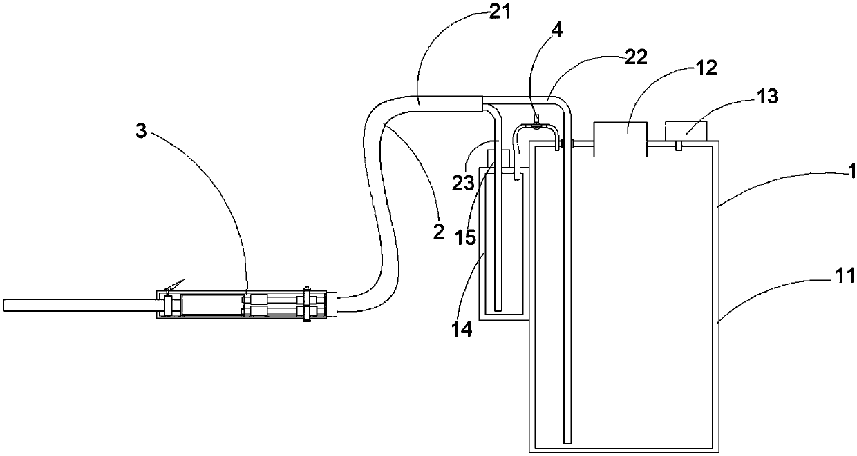
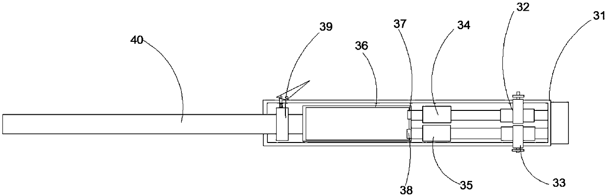
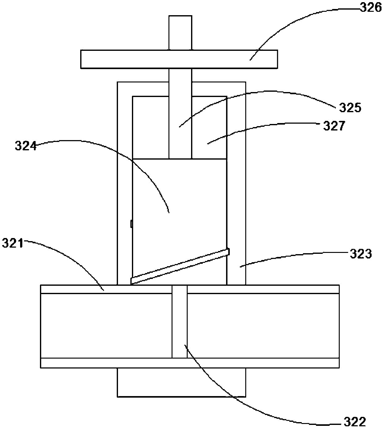
[0020] The embodiment of the invention discloses a car washer capable of adjusting the ratio of washing liquid, such as figure 1 with figure 2 As shown, it includes a liquid storage mechanism 1, an infusion mechanism 2, a liquid mixing mechanism 3. The liquid storage mechanism 1 includes a water storage tank, a liquid storage tank, and a three-way pressure relief valve 4, and the liquid storage tank is installed on one side of the water storage tank, The water storage tank includes a first tank body 11, a first upper cover 12, and a pressurizer 13. The first upper cover 12 is installed on the first tank body 11, and the pressurizer 13 is connected to the first tank body 11. Connected; the liquid storage tank includes a second tank 14, a second upper cover 15, the second upper cover 15 is installed on the second tank 14; the three-way pressure relief valve 4 is provided with a first air port , The second air port, the third air port, the first air port, the second air port are respectively connected to the first box body 11, the second box body 14; the infusion mechanism 2 includes a water delivery pipe 22, an infusion pipe 23, a sleeve 21 , The sleeve 21 is sleeved on the outside of the water pipe 22 and the infusion pipe 23, one end of the water pipe 21 is inserted into the first box 11, and one end of the infusion pipe 23 is inserted into the second box 14; The mixing mechanism 3 includes a housing 31, a first flow control valve 32, a second flow control valve 33, a first check valve 34, a second check valve 35, a mixing chamber 36, a liquid outlet pipe 40, and a liquid outlet valve 39. , The first flow control valve 32, the second flow control valve 33, the first one-way valve 34, the second one-way valve 35, and the liquid mixing chamber 36 are installed in the housing 31, and the other end of the water pipe 22, The first flow control valve 32, the first one-way valve 34, and the mixing chamber 36 are connected in sequence. The other end of the infusion pipe 23, the second flow control valve 33, the second one-way valve 35, and the mixing chamber 36 are connected in sequence. One end of the liquid outlet pipe 40 is inserted into the housing 31 and connected to the liquid mixing chamber 36, and the liquid outlet valve 39 is installed on the liquid outlet pipe 40.
[0021] Optional, such as image 3 As shown, the first flow control valve 32 includes a first flow tube 321, a first choke 322, a first fixing clip 323, a first screw adjusting column 324, a first transmission rod 325, and a first spiral disc 326, The first flow tube 321 is provided with a through hole, the lower end of the first choke plug 322 is inserted into the through hole, and the upper end of the first choke plug 322 is connected to the bottom of the first spiral adjusting column 324. The surface of the first screw adjustment post 324 has threads, and the first fixing clip 323 is provided with an internal thread post cavity 327 matching the first screw adjustment post 324. The first screw adjustment post 324 is screw-mounted on the first screw adjustment post 324. In the internal threaded column cavity 327 of the fixing clip 323, the lower end of the first transmission rod 325 is inserted into the first fixing clip 323 and connected to the upper end of the first screw adjusting column 324. The upper end of the first transmission rod 325 is connected to the A spiral disc 326 is connected to the center, the first flow tube 321 is provided with a diversion cavity, the cross section of the diversion cavity is rectangular, the height of the first screw adjusting column 324 is connected with the internal thread of the first fixing clip 323 The height difference of the column cavity 327 is not less than the height of the rectangular cross-section of the diversion cavity, and the moving distance of the first spiral adjusting column 324 after one revolution is the same as the height of the cross-section rectangle of the diversion cavity.
[0022] Among them, such as image 3 As shown, when the first flow control valve 32 is used, the first screw adjustment column 324 is controlled to rotate and descend in the first fixing clip 323 through the first spiral disc 326, so that the first choke plug 322 is filled into the first flow tube 321 In this method, the flow area of the first flow tube 321 is reduced, thereby controlling the amount of liquid that can flow per unit time.
[0023] In particular, the second flow control valve adopts the structure of the first flow control valve 32, and the second flow control valve includes a second flow tube, a second choke plug, a second fixing clip, a second screw adjusting column, and a second The transmission rod, the second spiral disc, the second flow tube is provided with a through hole, the lower end of the second choke plug is inserted into the through hole, and the upper end of the second choke plug is connected to the bottom of the second spiral adjusting column The second screw adjustment column has threads on the surface, the second fixing clip is provided with an internal thread column cavity matching the second screw adjustment column, and the second screw adjustment column is screwed on the second fixing The lower end of the second transmission rod is inserted into the second fixing clamp and connected with the upper end of the second screw adjustment column, and the upper end of the second transmission rod is connected with the center of the second spiral disc. The second flow tube is provided with a diversion cavity, the cross section of the diversion cavity is rectangular, and the height difference between the height of the second screw adjustment column and the cavity height of the second fixing clamp internal thread column is not less than the guide The height of the cross section of the flow cavity is rectangular, and the moving distance of the second spiral adjustment column after one revolution is the same as the height of the cross section of the diversion cavity.
[0024] Particularly, the outer edge of the first spiral disk 326 is provided with a plurality of digital identifiers, and the angle between the adjacent digital identifiers and the center of the circle is the same, and the outer edge of the second spiral disk is provided with a plurality of numbers. Mark, the angle between each adjacent digital mark and the center of the circle is the same.
[0025] Optionally, a first atomization head 37 and a second atomization head 38 are further provided in the mixing chamber 36, and the first atomization head 37 is connected to the first one-way valve 34, and the second atomization The head 38 is connected to the second one-way valve 35.
[0026] Among them, the first atomizing head 37 and the second atomizing head 38 are in the structure of atomizing nozzles, and the corresponding liquid forms atomized droplets when passing through the atomizing nozzles, so that the water and the lotion can be fully mixed, thereby improving the cleaning effect . The outer edge of the first spiral disc 326 is provided with 10 marks 0, 10, 20, 30, 40, 50, 60, 70, 80, and 90, and the angle between each adjacent mark and the center of the circle is the same. When the flow control valve 32 is closed, the 0 mark of the first spiral disc 326 is facing the direction of liquid flow. When the first spiral disc 326 rotates once, the first flow control valve 32 is fully opened, and the 0 mark of the first spiral disc 326 remains Towards the direction of liquid flow. The second flow control valve 33 still adopts the same structure as the first flow control valve 32.
[0027] During the car washing process, the user can adjust the flow capacity of the first flow control valve 32 and the second flow control valve 33 by rotating the first spiral disc 326 and the second spiral disc as needed; control the three-way pressure relief Valve 4 connects the first air port and the second air port, and closes the third air port. The pressurizer 13 pressurizes the water storage tank so that the air pressure in the water storage tank and the liquid storage tank are the same. Open the liquid outlet valve 39 to make the water and wash The liquid flows into the liquid mixing chamber 36 through respective output systems for mixing, and is sprayed out through the liquid outlet pipe 40 to clean the car. After the cleaning is completed, the second flow control valve 33 is closed by rotating the second spiral disc, and the three-way pressure relief valve 4 is controlled to close the first air port and the second air port, and the second air port and the third air port are connected to make Only the high air pressure in the water storage tank allows the water to flow into the mixed liquid cavity 36 through the output system, and the original solution in the mixed liquid cavity is washed and sprayed to realize the washing of the surface of the car with water.
[0028] The embodiment of the present invention uses a water storage tank and a liquid storage tank to realize the separation of water and car washing liquid, so that the water in the car washing device and the car washing liquid are isolated from each other and pollution is avoided. At the same time, the embodiment of the present invention adopts the first flow control valve and the second flow control valve to realize the adjustment of the output ratio of water and car washing liquid, thereby achieving the effect of controlling the output ratio of water and car washing liquid, and avoiding the pre-configuration process. Simplify the car wash process.
[0029] Optionally, the sleeve 21 is a polyurethane foam tube.
[0030] In the embodiment of the present invention, by using a polyurethane foam tube, the sleeve 21 can effectively protect the water delivery pipe 22 and the infusion pipe 23 and avoid damage to the water delivery pipe 22 and the infusion pipe 23 during use.
[0031] Optionally, the pressurizer 13 is an air pump.
[0032] The air pump in the embodiment of the present invention is a pressurized air pump, which realizes the automatic inflation function.
[0033] Optionally, a pressure gauge is also provided on the water storage tank.
[0034] Optionally, a manual air pump is also provided on the first upper cover 12.
[0035] By adopting a manual air pump in the embodiment of the present invention, the user can use hand pressure to increase the air pressure in the liquid storage mechanism 1 as needed to achieve pressurization and promote the flow of liquid into the liquid mixing mechanism 3 for mixed use.
[0036] Optionally, a safety valve is further provided on the first box body 11.
[0037] Finally, it should be noted that the above embodiments are only used to illustrate the technical solutions of the present invention and not to limit them. Although the present invention has been described in detail with reference to the above embodiments, those of ordinary skill in the art should understand that the technical personnel should read this After the application specification, the specific implementation of the present invention can still be modified or equivalently replaced, but these modifications or changes do not depart from the protection scope of the pending claims of the present invention.