Structure for controlling front and rear connection of train during running and working method thereof
A running and train technology, applied in railway car body parts, railway couplings, railway auxiliary equipment, etc., can solve the problems of unstable connection process, prone to rear-end collisions, and poor control of the speed of rear trains. The connection process is stable and the effect of avoiding rear-end collisions
- Summary
- Abstract
- Description
- Claims
- Application Information
AI Technical Summary
Problems solved by technology
Method used
Image

Examples
Embodiment Construction
[0022] The present invention will be further described in detail below in conjunction with the accompanying drawings and examples. The following examples are explanations of the present invention and the present invention is not limited to the following examples.
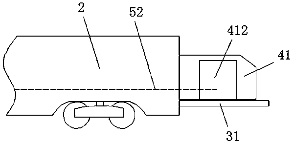
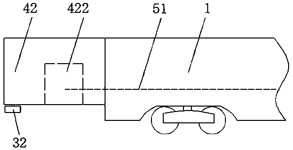
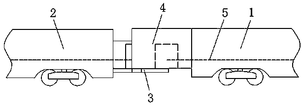
[0023] see Figure 1-Figure 6 , the embodiment of the present invention includes a train set, and the train set includes a front train 1 , a rear train 2 , a connection mechanism 3 , a connection carriage 4 and a transportation mechanism 5 .
[0024] The front train 1 and the rear train 2 themselves all have power, and the front train 1 and the rear train 2 are connected by the connecting mechanism 3 when running.
[0025] The connecting mechanism 3 comprises a rack 31, a gear 32 and a control system. The rack 31 and the gear are installed on the tail of the train 1 ahead and the head of the train 2 behind, that is to say, the rack 31 is installed on the tail of the train 1 ahead. When, gear 32 is installed on the ...
PUM
 Abstract
Description
Claims
Application Information
PatSnap Eureka turns technology decisions into work you can execute. Powered by our Innovation Knowledge Graph, it runs expert workflows across engineering, life sciences, materials and intellectual property. Get your review-ready output in minutes.


