Vehicle rear collision early warning system based on optical multi-view vision

A multi-eye vision and rear-end collision warning technology, which is applied in the field of vehicle safety, can solve the problems of expensive instruments, large difference in safety values ​​between small cars and large vehicles, and equipment costs that prevent rear-end collision systems from being widely used, so as to reduce costs and avoid rear-end collision accidents Effect

Pending Publication Date: 2017-09-15
LINGNAN NORMAL UNIV
View PDF1 Cites 9 Cited by
  • Summary
  • Abstract
  • Description
  • Claims
  • Application Information

AI Technical Summary

Problems solved by technology

However, the current technology is far from enough to judge the relative speed and distance for early warning. It can be understood that the safety distance and speed set by these systems are fixed within a small area, but the safety value of small cars and large cars is natural. The difference is still relatively large
Existing technology and equipment do not take this into consideration, the actual data obtained is poor in availability and cannot provide accurate and effective information for the driver, and the anti-rear-end collision does not have the desired effect
Simultaneously the used instrument of existing method is expensive, and common family is difficult to afford high equipment cost and will also cause existing anti-rear-collision system to be unable to generally use

Method used


Image

  • Vehicle rear collision early warning system based on optical multi-view vision
  • Vehicle rear collision early warning system based on optical multi-view vision
  • Vehicle rear collision early warning system based on optical multi-view vision

Examples


Embodiment Construction

[0023] Since the accompanying drawings are used to provide a further understanding of the present invention, the schematic embodiments of the present invention and their descriptions are used to explain the present invention, and do not constitute an improper limitation of the present invention.

[0024] The specific implementation manner of the present invention will be further described below in conjunction with the accompanying drawings.

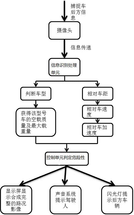
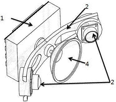
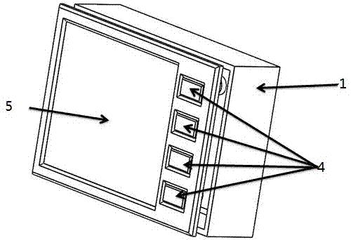
[0025] On the expressway, the driving speed of the car is fast. Due to the bad driving habits of the driver, he often only pays attention to the driving conditions of the vehicles in front and ignores the driving conditions of the vehicles coming from behind. Therefore, rear-end collision accidents are prone to occur, and serious car crashes even cause fatalities. . This embodiment provides a vehicle rear-end collision warning system based on optical multi-eye vision. It mainly includes a control box 1 and a U-shaped bracket 2 connected ...


PUM


Abstract

The invention discloses a vehicle rear collision early warning system based on optical multi-view vision. The system comprises an information collection unit, an information recognition and processing unit, a control unit and an early warning unit. The information collection unit is used for collecting vehicle rear image information and measuring a relative distance between the vehicle itself and a vehicle behind. The information recognition and processing unit is connected with the information collection unit and at least comprises a vehicle type recognition module and a vehicle state determination module. Image information and data information are pre-stored in the vehicle type recognition module. The vehicle type recognition module determines the type of the vehicle according to the information collected by the information collection unit. The vehicle state determination module determines the distance, relative speed and relative accelerated speed of vehicles according to the information collected by the information collection unit. The control unit is connected with the image recognition and processing unit, determines whether a risk that the vehicle collides with the rear vehicles exists according to the information processed by the image recognition and processing unit, and gives out a command to the early warning unit according to the determination result. The early warning unit is connected with the control unit and comprises a sound early warning module and a light early warning module.

Description

technical field [0001] The invention relates to the technical field of vehicle safety, in particular to a vehicle rear-end collision warning system. Background technique [0002] At present, most of the automobile anti-rear collision systems are applied to the distance measurement. The commonly used measurement methods are: ultrasonic distance measurement, infrared distance measurement, laser distance measurement. The principle of ultrasonic distance measurement is to use the known propagation speed of ultrasonic waves in the air to measure the time it takes for the sound waves to encounter obstacles and reflect back after they are emitted, and to calculate the actual distance from the emission point to the obstacle based on the time difference between emission and reception. The work of the infrared range finder uses the principle of non-diffusion when the infrared ray propagates. When the infrared ray is emitted from the range finder and hits the reflector, it is reflected...

Claims


Application Information

Patent Timeline
Patent Type & Authority Applications(China)
IPC IPC(8): G08G1/16
CPCG08G1/166
Inventor 宫凯朱伟
Owner LINGNAN NORMAL UNIV
Why Eureka
Try Eureka