Oscillatory type automobile rear collision alarming device

An alarm device and vibration technology, applied in the direction of alarm, signal device, signal device, etc., can solve the problems of difficult implementation, high cost, and large vehicle changes, and achieve good alarm effect, small negative impact, and good compatibility Effect

Inactive Publication Date: 2008-07-30
TSINGHUA UNIV
View PDF0 Cites 9 Cited by
  • Summary
  • Abstract
  • Description
  • Claims
  • Application Information

AI Technical Summary

Problems solved by technology

The advantage of this method is: it is relatively simple to implement, the cost is low, the driver can easily receive the alarm information, and the interference to normal driving is small; If the sound is too loud, it may interfere with the driver or passengers; if the sound is too small, the driver cannot hear the alarm, and the alarm effect cannot be achieved
Its disadvantages are: the real-time alarm is not enough. In addition, the odor release device is complicated, and different drivers have different sensitivity to taste. When the driver is drinking or fatigued, the alarm effect cannot be satisfied. Therefore, this alarm method little practical application
The current technology is to provide alarm information to the driver through the vibration of the driver's seat or the vibration of the steering wheel. The disadvantages of these vibration methods are mainly that the structure of the alarm device is complicated, the cost is high, and the vehicle is greatly modified, so it is difficult to implement.

Method used


Image

  • Oscillatory type automobile rear collision alarming device
  • Oscillatory type automobile rear collision alarming device
  • Oscillatory type automobile rear collision alarming device

Examples


Embodiment Construction

[0035] Further illustrate the present invention below in conjunction with accompanying drawing.

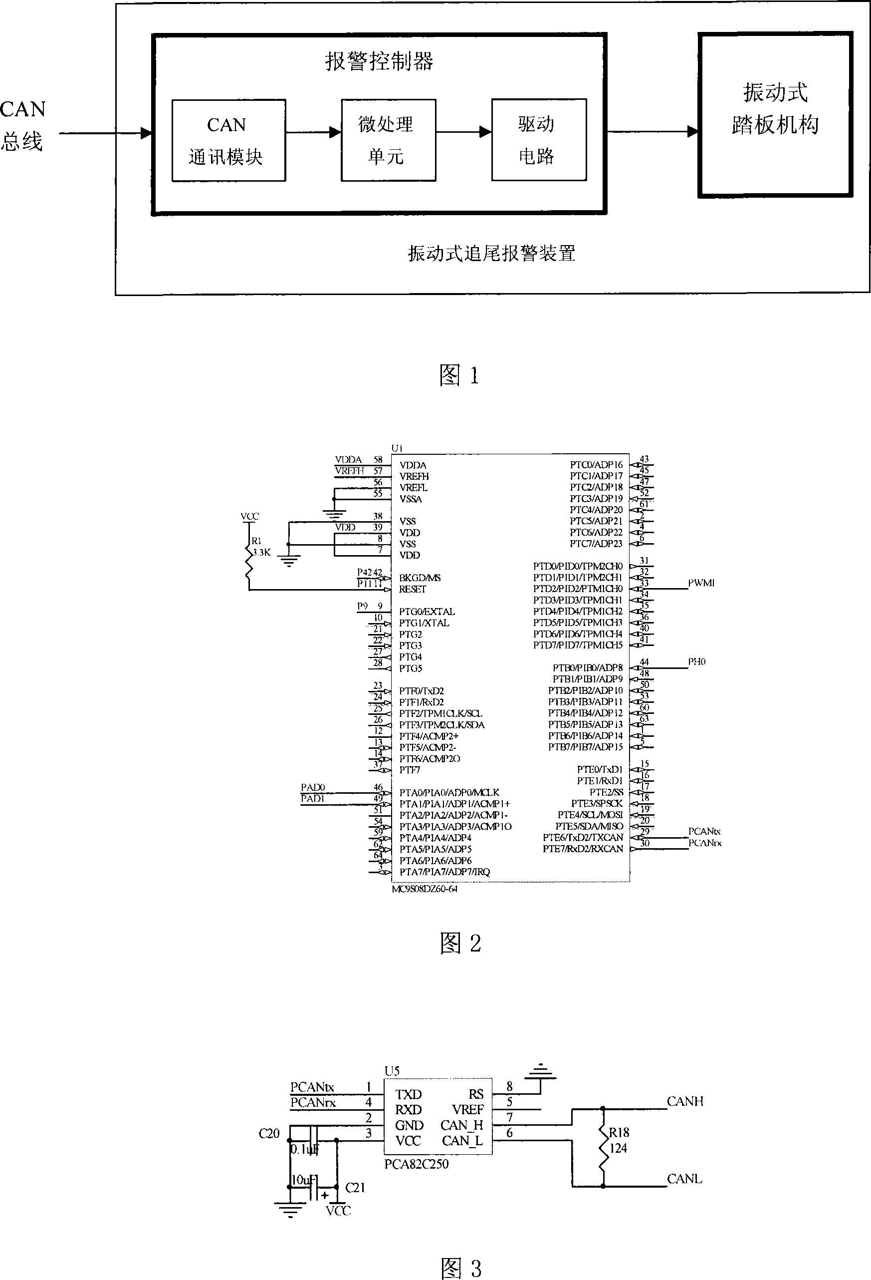
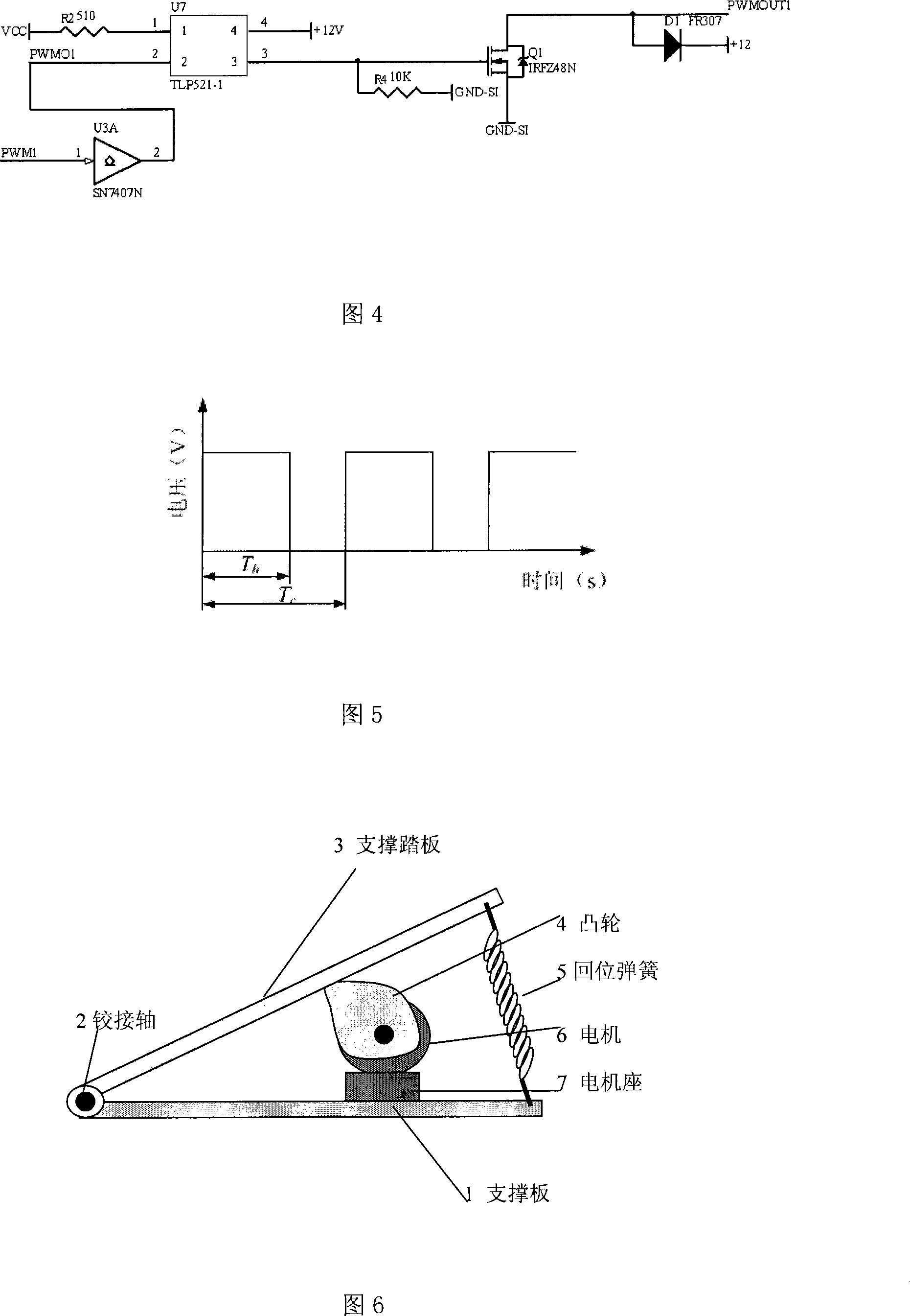
[0036]Fig. 1 is a structural schematic diagram of the present invention, including two parts of an alarm controller and a vibrating pedal mechanism. The alarm controller is an integrated circuit board including a micro-processing unit, a CAN communication module and a driving circuit module. What the microprocessing unit adopts is Motorola's 8-bit single-chip microcomputer MC9S08DZ60 chip, and its circuit schematic diagram is shown in Fig. 2 . (Fig. 2 is the schematic diagram of the micro-processing unit circuit in the alarm controller.) The CAN communication pins PCANtx and PCANrx of the single-chip microcomputer and the pulse modulation pin PWM1 are mainly drawn out in the present invention. The microcontroller needs to be powered by a regulated DC 5V voltage.

[0037] In order to realize communication through the CAN bus and provide a general-purpose CAN interface, the CAN co...


PUM


Abstract

The invention provides an oscillatory type automobile rear-end alarming device and belongs to the field of safe driving assisting technology of automobile. The invention comprises an alarm controller and an oscillatory type pedal mechanism. The alarm controller comprises a CAN communication module, a microprocessing unit and a drive circuit. PCANtx and PCANrx pins of the CAN communication module PCA82C250 are connected with PCANtx and PCANrx pins of the SCM of the microprocessing unit MC9S08DZ60. The CAN communication module is provided with a general-purpose type interface, and can be incorporated into a vehicle-mounted CAN network. The input PWM1 of the drive circuit SN7407N is connected with the corresponding output of the microprocessing unit. The output port of the drive circuit is connected with the motor of the pedal mechanism. The invention gives an alarm through the vibration of feet of a driver with little influence on the driver. Graded alarm can be adopted; the mechanical structure is simple and can be achieved easily with low cost, and the invention is highly compatible and humanized, and facilitates processing and refitting of large quantities.

Description

technical field [0001] A vibration-type automobile rear-end collision alarm device is applied in an automobile rear-end collision alarm system to provide alarm information for drivers, and belongs to the technical field of automobile safety auxiliary driving. Background technique [0002] Rear-end collision accidents account for a considerable proportion of traffic accidents, and the car rear-end collision warning system in driver assistance technology can detect rear-end collision danger and remind the driver, effectively reducing rear-end collision accidents. The rear-end collision alarm system is generally composed of sensors and alarm devices. The sensors include radars and cameras to obtain information such as the relative distance and relative speed of the vehicle in front. warning message. The present invention is mainly designed for the alarm device therein. Since the rear-end collision alarm system directly interacts with the driver, the alarm method has a very im...

Claims


Application Information

Patent Timeline
Patent Type & Authority Applications(China)
IPC IPC(8): G08B6/00G08B21/02G08B25/04G08G1/16B60Q9/00
Inventor 王建强李克强张磊张德兆杨波李升波
Owner TSINGHUA UNIV
Why Eureka
Try Eureka