Trolley type aluminum alloy aging furnace

An aluminum alloy, trolley-type technology, used in furnaces, furnace types, heat treatment furnaces, etc., can solve the problems of uneven heat flow and temperature, low mechanical strength of workpieces, slow heating efficiency of workpieces, etc., to achieve convenient operation and labor saving, avoid heat Quick churn, easy-to-use effects

Inactive Publication Date: 2019-03-29
XUZHOU LINT TOP CABLE TECH CO LTD
View PDF5 Cites 7 Cited by
  • Summary
  • Abstract
  • Description
  • Claims
  • Application Information

AI Technical Summary

Problems solved by technology

The trolley and the furnace body are two independent components. The furnace body has a furnace door that can be opened or closed for the trolley to enter and exit the furnace. The existing trolley-type aluminum alloy aging furnace has the following defects: 1. .The heat flow temperature inside the existing trolley-type aluminum alloy aging furnace is not uniform, which easily leads to low mechanical strength of the processed workpiece; 3. The existing trolley-type aluminum alloy aging furnace has poor sealing performance, and the furnace The internal heat is easy to leak from the connection between the trolley and the furnace body, resulting in slow heating efficiency and low quality of the workpiece. 3. The existing trolley-type aluminum alloy aging furnace is not convenient to use with the trolley, which greatly reduces work efficiency and prolongs working time. To this end, we propose a trolley-type aluminum alloy aging furnace

Method used


Image

  • Trolley type aluminum alloy aging furnace
  • Trolley type aluminum alloy aging furnace
  • Trolley type aluminum alloy aging furnace

Examples


Embodiment Construction

[0024] The following will clearly and completely describe the technical solutions in the embodiments of the present invention with reference to the accompanying drawings in the embodiments of the present invention. Obviously, the described embodiments are only some, not all, embodiments of the present invention. Based on the embodiments of the present invention, all other embodiments obtained by persons of ordinary skill in the art without making creative efforts belong to the protection scope of the present invention.

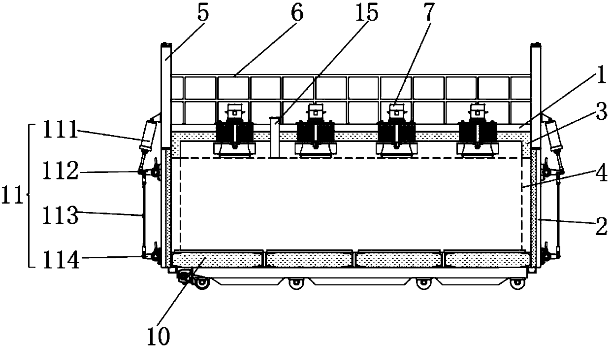
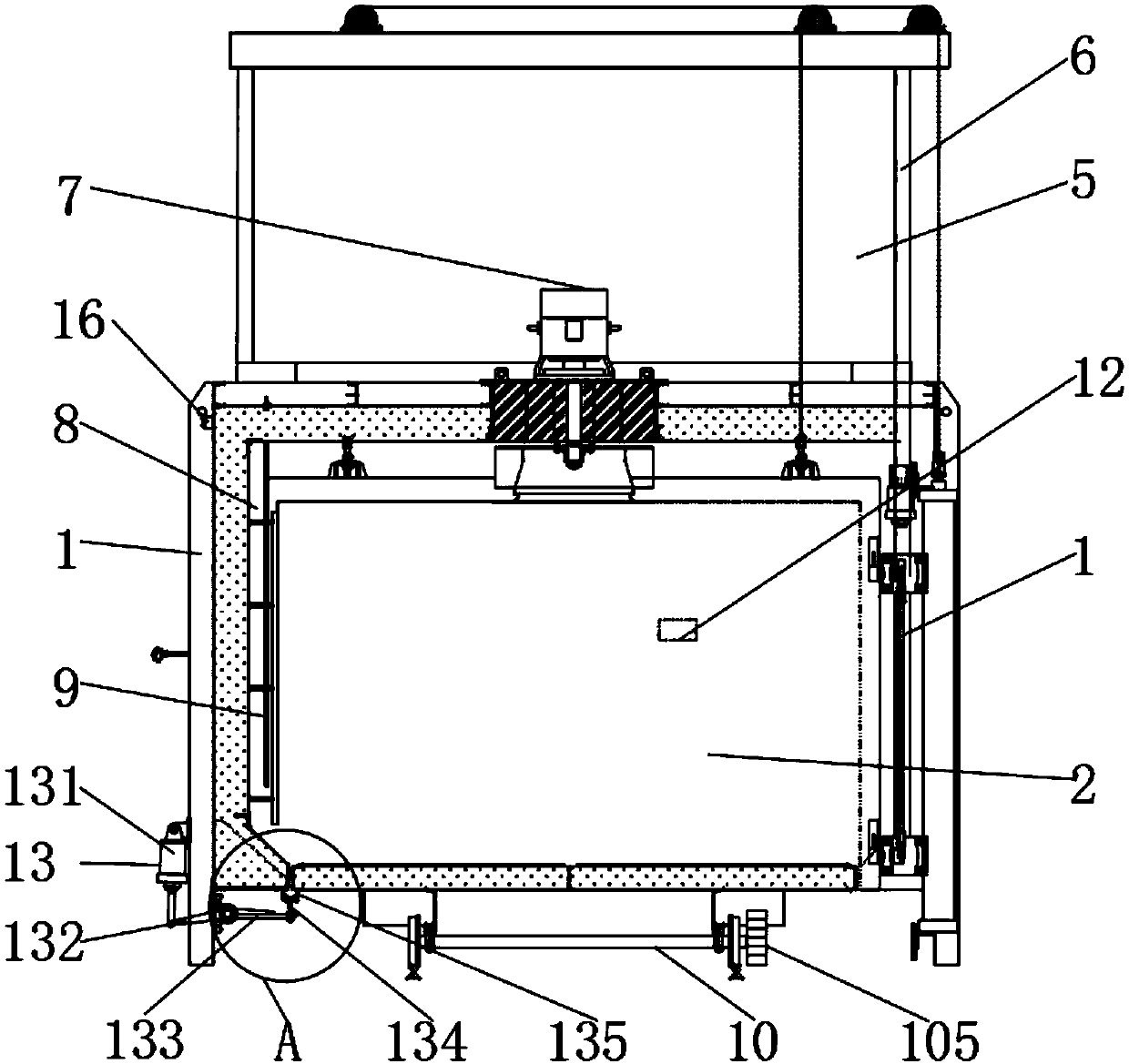
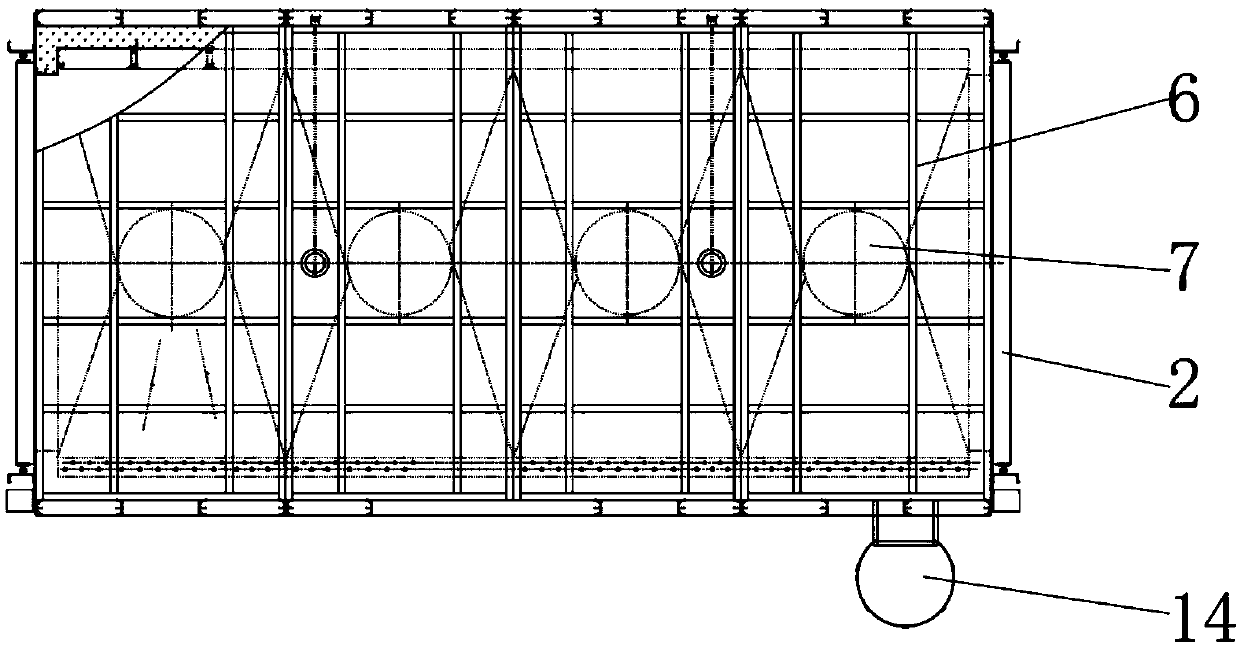
[0025] see Figure 1-5, the present invention provides a technical solution: a trolley-type aluminum alloy aging furnace, including a box body 1 and a damper device 16, which can introduce external air into the interior to keep the internal and external air pressure stable, and the damper device 16 is located in the box body 1 At the upper position of the front, the bottom of the box body 1 is a hollow structure, allowing the main body of the trolley 1 to ente...


PUM

PropertyMeasurementUnit
thicknessaaaaaaaaaa
thicknessaaaaaaaaaa

Abstract

The invention discloses a trolley type aluminum alloy aging furnace, and belongs to the technical field of aging furnaces. The trolley type aluminum alloy aging furnace comprises a box body and an airadjusting door device; furnace doors with the same structure are hinged to the positions through holes, four groups of vertical centrifugal hot air circulating fans are uniformly arranged on the topof the box body from left to right, and a fan shaft is arranged at the bottom end of each of the four groups of centrifugal hot air circulating fans; and a ventilating duct is arranged between a heatpreservation layer and an inner container, a trolley main body is arranged at the bottom of the part which is located between the two groups of furnace doors, furnace door mechanisms with the same structure are arranged on the outer sides of the two groups of vertical plates respectively, and a sealing mechanism is arranged at the bottom of the outer wall at the rear side of the box body. According to the trolley type aluminum alloy aging furnace, four groups of vertical centrifugal hot air circulating fans are adopted, the heat emitted by a heating element is forced to flow circularly, so that the temperature in the furnace is promoted to be uniform; and meanwhile, the heat preservation layer and the heat preservation material layer can well preserve heat, so that the heat can be prevented from being rapidly lost, and the heating quality and efficiency of a workpiece in the furnace can be greatly improved.

Description

technical field [0001] The invention relates to the technical field of aging furnaces, in particular to a trolley-type aluminum alloy aging furnace. Background technique [0002] At present, the known trolley furnaces are all composed of a body of furnace and a trolley. The trolley and the furnace body are two independent components. The furnace body has a furnace door that can be opened or closed for the trolley to enter and exit the furnace. The existing trolley-type aluminum alloy aging furnace has the following defects: 1. .The heat flow temperature inside the existing trolley-type aluminum alloy aging furnace is not uniform, which easily leads to low mechanical strength of the processed workpiece; 3. The existing trolley-type aluminum alloy aging furnace has poor sealing performance, and the furnace The internal heat is easy to leak from the connection between the trolley and the furnace body, resulting in slow heating efficiency and low quality of the workpiece. 3. Th...

Claims


Application Information

Patent Timeline
Patent Type & Authority Applications(China)
IPC IPC(8): C21D9/00C22F1/04
CPCC21D9/00C22F1/04
Inventor 佟畅朱庆龙尹婷
Owner XUZHOU LINT TOP CABLE TECH CO LTD
Why Eureka
Try Eureka