Door and window system

A door, window, and fan frame technology, which is applied to the door/window accessories, the arrangement of the wings, the connection of the handle, etc., can solve the problems of incoherent movement, inconvenient use, and size that cannot be made small, so as to reduce locking and unlocking errors. Operation phenomenon, guaranteed appearance effect, simple and convenient operation effect

Pending Publication Date: 2019-03-29
HUNAN GOLDWELL NEW MATERIALS TECH CO LTD
View PDF0 Cites 0 Cited by
  • Summary
  • Abstract
  • Description
  • Claims
  • Application Information

AI Technical Summary

Problems solved by technology

For the above-mentioned locking mechanism, on the one hand, the front of the fan frame must have a base for the installation of the lock handle, so that the size of the fan frame on the visible surface (positive direction) cannot be reduced, that is, the slimming of the product cannot be guaranteed; On the one hand, the user has the action of pushing and pulling the lock handle (opening and closing of the fan body) and rotating the lock handle (locking and unlocking) during operation, and these two actions are in two different directions, resulting in incoherent actions and poor use. Inconvenient, and it is easy to cause locking and unlocking not in place

Method used


Image

  • Door and window system
  • Door and window system
  • Door and window system

Examples


Embodiment 1

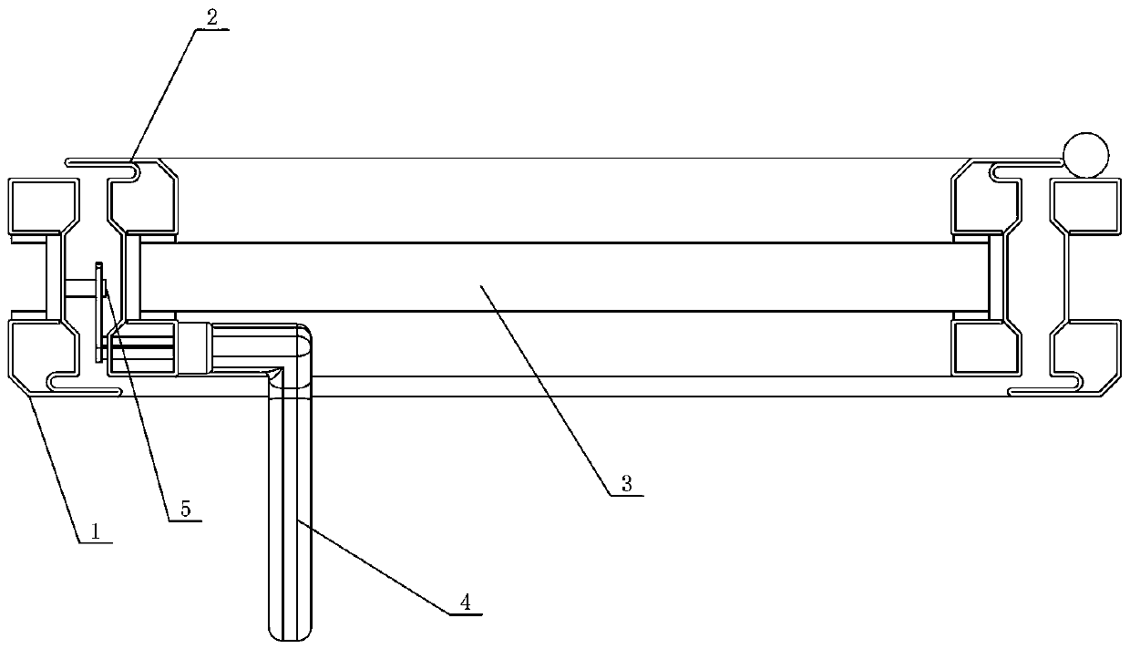
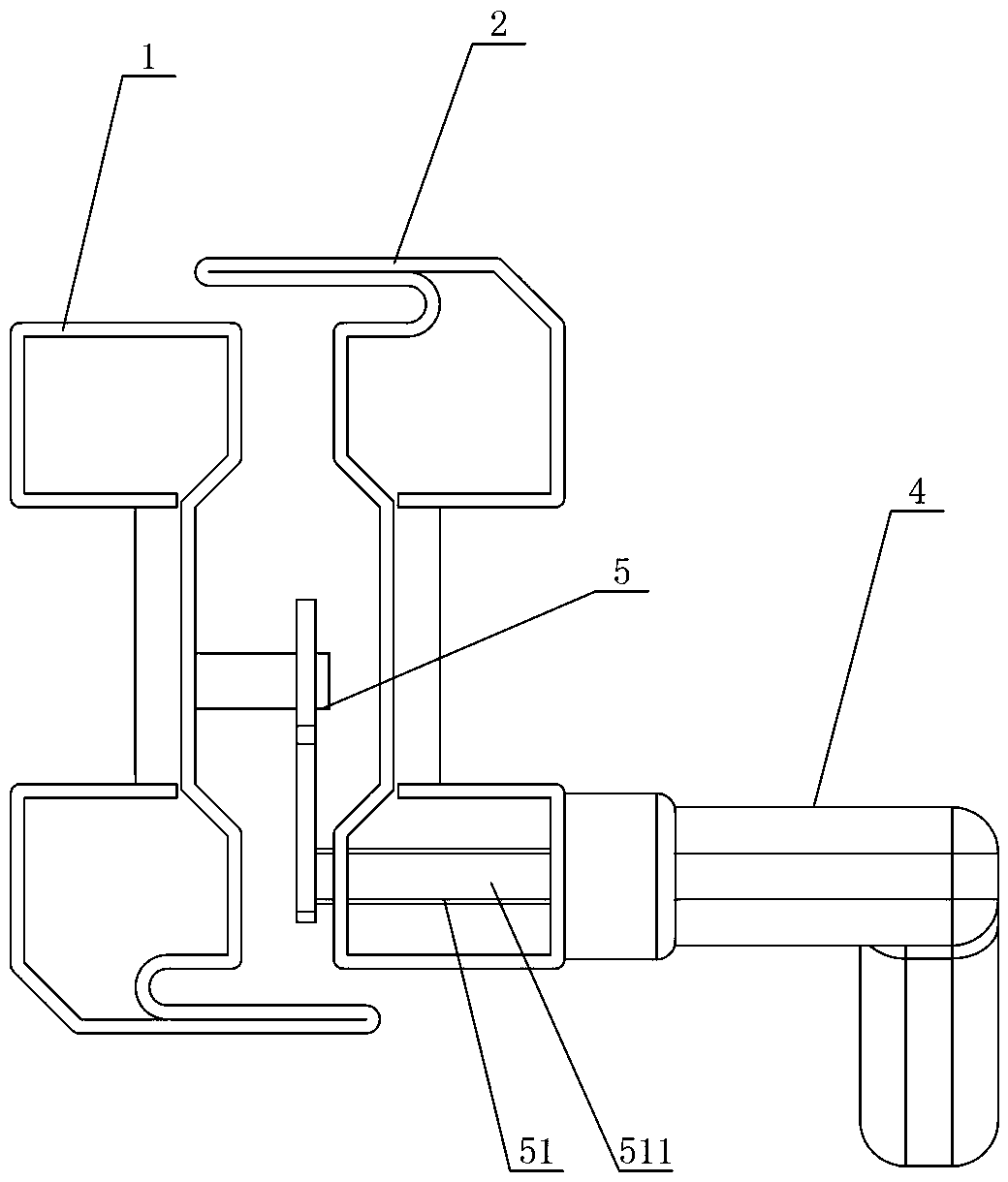
[0035] Figure 1 to Figure 4 Shows the first embodiment of the door and window system of the present invention, including a fixed frame 1, a fan frame 2 and a fan body 3, the fan body 3 is fixed in the fan frame 2, one side of the fan frame 2 is hinged with the fixed frame 1, and the other One side is set as the opening and closing side, and the fan frame 2 is provided with a lock handle 4 along the inner side of the opening and closing side, and a locking mechanism 5 is installed between the fan frame 2 and the fixed frame 1, and the locking mechanism 5 is connected with the lock handle 4 When the operation lock handle 4 is pulled inward, the fan frame 2 is closed. After the fan frame 2 is closed and the operation lock handle 4 is lifted up, the locking mechanism 5 is locked. After the locking mechanism 5 is locked and the operation lock handle 4 is pressed down When the locking mechanism 5 is unlocked, and the lock handle 4 is pushed outward after the locking mechanism 5 is ...

Embodiment 2

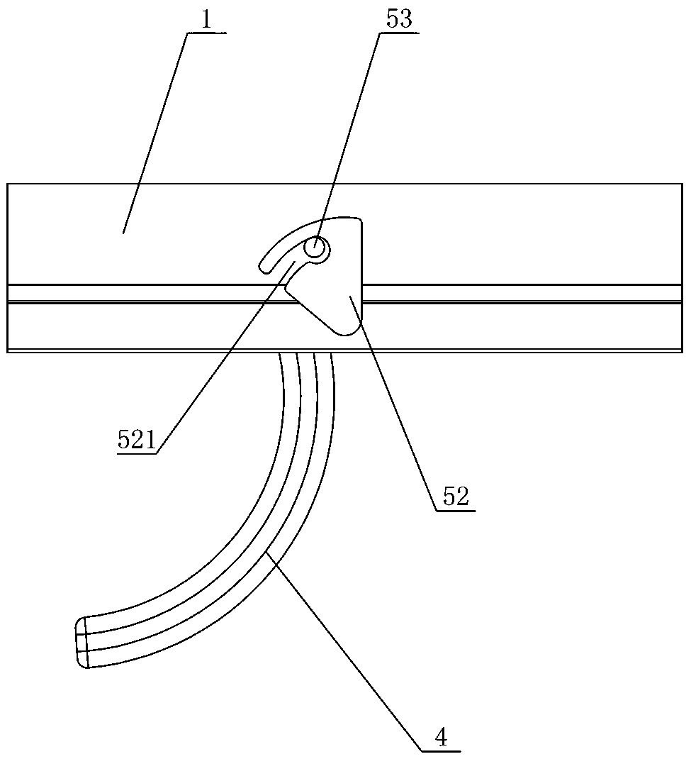
[0040] Figure 5 to Figure 8 A second embodiment of the door and window system of the present invention is shown, which is basically the same as the first embodiment. The only difference is that in this embodiment, the transmission member 51 includes a transmission rod 511, a transmission gear 512 and a transmission rack 513, the movable lock body 52 is set as a lock cylinder, the fixed lock body 53 is provided with a stopper, and the transmission rod 511 is movably installed on the fan. The frame 2 is connected with the lock handle 4, the transmission gear 512 is connected with the transmission rod 511, the transmission rack 513 is movably installed on the fan frame 2 and meshed with the transmission gear 512, the lock column is fixed on the transmission rack 513, and the lock handle 4. When lifting, the transmission rod 511 drives the lock column through the transmission gear 512 and the transmission rack 513 to move to contact with the block to lock. When the lock handle 4 ...

Embodiment 3

[0044] Figure 9 to Figure 12 A third embodiment of the door and window system of the present invention is shown, which is basically the same as the second embodiment. The only difference is that in this embodiment, the transmission member 51 includes a transmission rod 511, a transmission fork 514 and a transmission slider 515, the transmission slider 515 is provided with a transmission lever 516, and the movable lock body 52 is set as a lock cylinder, and the fixed lock The body 53 is provided with a block, the transmission rod 511 is movably installed on the fan frame 2 and connected with the lock handle 4, the transmission fork 514 is connected with the transmission rod 511, and the transmission slider 515 is movably installed on the fan frame 2 and passed through the transmission lever 516. It is connected with the transmission fork 514, and the lock cylinder is fixed on the transmission slider 515. When the lock handle 4 is lifted, the transmission rod 511 drives the loc...


PUM


Abstract

The invention discloses a door and window system. The door and window system comprises a fixing frame, a sash frame and a sash body. The sash body is fixedly arranged in the sash frame, one side of the sash frame and the fixing frame are movably hinged, the other side of the sash frame is an opening and closing side, a lock handle is arranged on the inner side edge of the opening and closing sideof the sash frame, a locking mechanism is arranged between the sash frame and the fixing frame, the locking mechanism is connected with the lock handle, when the lock handle is operated to be pulled inwards, the sash frame is closed, after the sash frame is closed and when the lock handle is operated to be lifted upwards, the locking mechanism carries out locking, after the locking mechanism carries out locking and the lock handle is operated to be pressed downwards, the locking mechanism is unlocked, and after the locking mechanism is unlocked and the lock handle is operated to be pushed outwards, the sash frame is opened. The door and window system has the advantages that the operation is easy and convenient, misoperation can be reduced, and the fineness of products can be achieved.

Description

technical field [0001] The invention mainly relates to the field of construction engineering, in particular to a door and window system. Background technique [0002] In the door and window system, the fan body is hinged on the fixed frame, which has the function of opening and closing, and a locking mechanism is installed on the fan body to ensure the locking function when the fan body is closed and the unlocking function when the fan body is opened. [0003] In the prior art, the lock handles of the locking mechanism are all set on the front of the fan body frame, that is, when the user operates the lock handle in the closed state, the lock handle is just facing the user. To achieve locking and unlocking, the user must also face the side direction It can only be achieved by rotating in one direction. For the above-mentioned locking mechanism, on the one hand, the front of the fan frame must have a base for the installation of the lock handle, so that the size of the fan f...

Claims


Application Information

Patent Timeline
Patent Type & Authority Applications(China)
IPC IPC(8): E06B3/32E05B3/00
CPCE06B3/32E05B3/00
Inventor 谢斌泉其他发明人请求不公开姓名
Owner HUNAN GOLDWELL NEW MATERIALS TECH CO LTD
Why Eureka
Try Eureka