
Switch drive circuit of DCDC converter

A technology for switching drive circuits and converters, applied in the direction of output power conversion devices, instruments, electrical components, etc., which can solve the problems of complex drive circuit application schemes and high costs, and achieve the effect of realizing built-in bootstrap capacitors and simplifying application schemes

Active Publication Date: 2020-08-28
SHANGHAI NATLINEAR ELECTRONICS CO LTD
View PDF3 Cites 0 Cited by
  • Summary
  • Abstract
  • Description
  • Claims
  • Application Information

AI Technical Summary

Problems solved by technology

[0005] In view of the shortcomings of the prior art described above, the purpose of the present invention is to provide a switch drive circuit for a DCDC converter, which is used to solve the problems of complex application schemes and high costs of the drive circuit in the prior art.

Method used


Image

  • Switch drive circuit of DCDC converter
  • Switch drive circuit of DCDC converter
  • Switch drive circuit of DCDC converter

Examples


Embodiment Construction

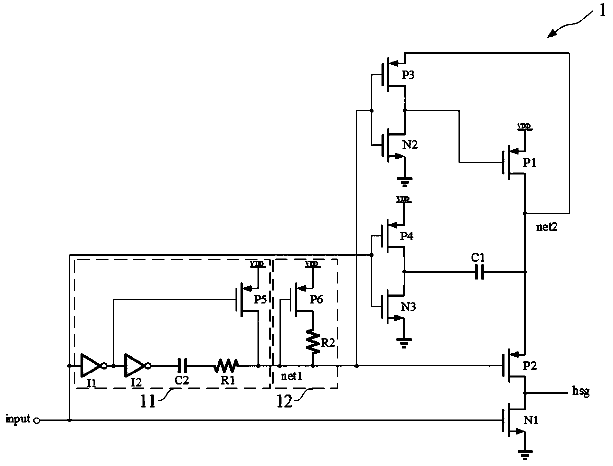
[0028] The following describes the implementation of the present invention through specific specific examples. Those skilled in the art can easily understand other advantages and effects of the present invention from the content disclosed in this specification. The present invention can also be implemented or applied through other different specific embodiments, and various details in this specification can also be modified or changed based on different viewpoints and applications without departing from the spirit of the present invention.

[0029] See Figure 2~Figure 7 . It should be noted that the illustrations provided in this embodiment only illustrate the basic idea of ​​the present invention in a schematic way, and the figures only show the components related to the present invention instead of the number, shape, and shape of the components in actual implementation. For size drawing, the type, quantity, and proportion of each component can be changed at will during actual ...


PUM


Abstract

The invention provides a switch drive circuit of a DCDC converter, comprising a control signal generation module for generating a control signal which is logically consistent with an input signal; wherein the first PMOS tube, the second PMOS tube and the first NMOS tube are connected in series between a power supply and the ground, grid electrodes of the first NMOS tube and the second PMOS tube are respectively connected with an input signal and a control signal, and drain electrodes of the first NMOS tube and the second PMOS tube output driving control signals; the third PMOS transistor and the second NMOS transistor are connected in series between the drain electrode of the first PMOS transistor and the ground, the grid electrodes of the third PMOS transistor and the second NMOS transistor are connected with a control signal, and the drain electrodes of the third PMOS transistor and the second NMOS transistor are connected with the grid electrode of the first PMOS transistor; the fourth PMOS transistor and the third NMOS transistor are connected in series between a power supply and the ground, the grid electrodes of the fourth PMOS transistor and the third NMOS transistor are connected with an input signal, and the drain electrodes of the fourth PMOS transistor and the third NMOS transistor are connected with the drain electrode of the first PMOS transistor through the firstcapacitor. The bootstrap capacitor and the drive circuit are combined, the capacitance value and the area of the bootstrap capacitor can be reduced to one thousandth to one thousandth of the traditional numerical value, the built-in bootstrap capacitor is realized, and the application scheme is simplified.

Description

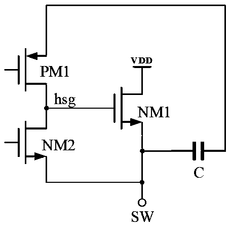
Technical field [0001] The present invention relates to the field of integrated circuit technology, in particular to a switch drive circuit of a DCDC converter. Background technique [0002] The DC / DC converter is a switching power supply chip. It uses the energy storage characteristics of capacitors and inductors to perform high-frequency switching through controllable switches (MOSFETs, etc.), and stores the input electrical energy in the capacitor (sense). When it is turned on, the electric energy is released to the load to provide energy. The output power or voltage capability is related to the duty cycle (the ratio of the switch on time to the entire switch cycle). Switching power supplies can be used for step-up and step-down. [0003] Step-down DCDC uses NMOS tube as the main power switch tube, such as figure 1 As shown, the PMOS tube PM1 and the NMOS tube NM2 are used as the output stage of the drive circuit, the PMOS tube PM1 is connected to the drain of the NMOS tube NM...

Claims


Application Information

Patent Timeline
Patent Type & Authority Applications(China)
IPC IPC(8): H02M3/156H02M1/32H02M1/088
CPCH02M1/088H02M1/32H02M3/156
Inventor 王冬峰何云夏虎刘桂芝
Owner SHANGHAI NATLINEAR ELECTRONICS CO LTD
Learn More