
Thrust rod ball joint and assembling method thereof

An assembly method and technology of thrust rods, applied in the direction of shafts and bearings, mechanical equipment, pivots, etc., can solve problems such as short service life and failure to meet vibration reduction requirements, so as to improve service life, not easy to wrinkle and unglue, and increase The effect of torque

Inactive Publication Date: 2019-03-29
株洲飞马橡胶实业有限公司
View PDF8 Cites 1 Cited by
  • Summary
  • Abstract
  • Description
  • Claims
  • Application Information

AI Technical Summary

Problems solved by technology

[0006] The technical problem to be solved by the present invention is that the rubber ball joint cannot meet the vibration damping requirements and short service life of the vibration damping part with a large variation range of radial stiffness and axial stiffness during use, and a thrust rod ball joint is provided.

Method used


Image

  • Thrust rod ball joint and assembling method thereof
  • Thrust rod ball joint and assembling method thereof

Examples


Embodiment Construction

[0032] The present invention will be further described below in conjunction with specific examples. It should be understood that one or more method steps mentioned in the present invention do not exclude that there are other method steps before and after the combined steps or other method steps can be inserted between these explicitly mentioned steps; it should also be understood that these The examples are only for illustrating the present invention and are not intended to limit the scope of the present invention.

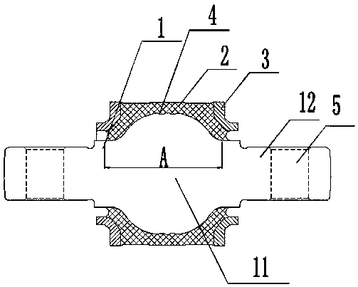
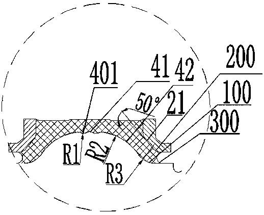
[0033] Such as Figure 1~2 as shown, figure 1 A thrust rod ball joint is provided for the present invention. The rubber ball joint includes a metal mandrel 1, a rubber layer 2 and a metal end cap 3 sequentially from the inside to the outside. The metal end cap 3 is vulcanized and bonded to both ends of the rubber layer 2. To prevent the extrusion of both ends of the rubber layer 2; the rubber layer 2 is vulcanized and bonded on the metal mandrel 1, and the bonde...


PUM


Abstract

The invention relates to a thrust rod ball joint and an assembling method thereof. The disclosed thrust rod rubber ball joint comprises a metal core shaft, a rubber layer and metal end covers; the metal end covers are arranged at the two ends of the rubber layer and are used for preventing rubber from extruding, the rubber layer is vulcanized and bonded on the metal core shaft, and the bonding part between the rubber layer and the metal core shaft is an arc surface; and the bulge top end of the metal core shaft is a corrugated part, and the corrugated part comprises at least two inner concavesurfaces. According to the rubber ball joint, the metal end covers are arranged at the two ends of the rubber layer, rubber bulging at the two ends of the rubber layer can be effectively reduced, andrubber bulging at the bonding part between the rubber layer and the metal core shaft can also be avoided; and meanwhile, the position of a rubber profile surface which is close to an outer sleeve andthe metal core shaft is not prone to wrinkling and cracking, and the service life of the rubber ball joint can be effectively prolonged.

Description

technical field [0001] The invention belongs to the technical field of rail vehicle elastic components, and in particular relates to a thrust rod ball joint and an assembly method thereof. Background technique [0002] The rubber ball joint is an excellent performance connecting element composed of rubber and metal. The ball joint mainly uses vulcanized rubber for shock absorption and buffering, and the metal parts play the role of support and installation interface. The ball joint can withstand complex working environments, including fatigue effects of multi-directional loads such as axial, radial, torsion, and deflection. and momentary mechanical shock. Therefore, rubber ball joints are widely used in the field of rail vehicles. At present, the most commonly used structure of the rubber ball joint is a metal mandrel, a rubber layer and a metal jacket from the inside to the outside, although the performance of this structure can basically meet the use of various working c...

Claims


Application Information

Patent Timeline
Patent Type & Authority Applications(China)
IPC IPC(8): F16C11/06
CPCF16C11/0685F16C11/0695
Inventor 王春龙熊雪辉谢建藩
Owner 株洲飞马橡胶实业有限公司
Learn More