Image pickup system

A camera system and image-side technology, applied in the field of camera systems, can solve problems such as difficulty in obtaining clear images, inability to achieve imaging effects, and complex shooting environments, reducing lens bulge, improving overall machine space utilization, and ensuring aesthetics. Effect

Pending Publication Date: 2022-02-15
ZHEJIANG SUNNY OPTICAL CO LTD
View PDF0 Cites 4 Cited by
  • Summary
  • Abstract
  • Description
  • Claims
  • Application Information

AI Technical Summary

Problems solved by technology

[0002]In recent years, consumers have higher and higher requirements for mobile phone shooting functions, such as face recognition, distance measurement and other functions. Complicated, it is difficult to get a clear image in a dim environment. The current mobile phone lens is limited in imaging in an environment with insufficient light, and cannot achieve a very clear imaging effect. At this time, the infrared lens can solve this problem very well

Method used


Image

  • Image pickup system
  • Image pickup system
  • Image pickup system

Examples


specific Embodiment 1

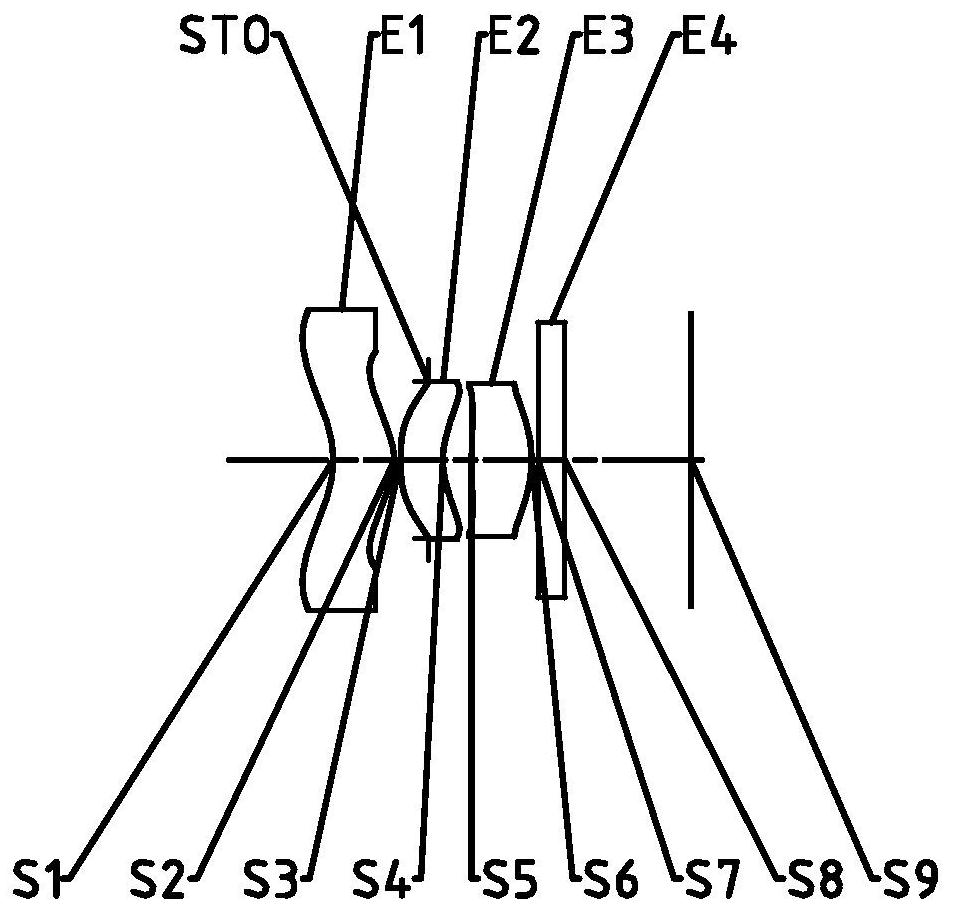
[0074] figure 1It is a schematic diagram of the lens group structure of Embodiment 1 of the camera system of the present invention. The camera system includes in sequence from the object side to the image side along the optical axis: a first lens E1, a diaphragm STO, a second lens E2, a third lens E3, a filter Slice E4 and imaging surface S9.

[0075] The first lens E1 has positive refractive power, its object side S1 is concave, and its image side S2 is convex. The second lens E2 has negative refractive power, its object side S3 is concave, and its image side S4 is concave. The third lens E3 has positive refractive power, its object side S5 is convex, and its image side S6 is convex. The filter E4 has an object side S7 and an image side S8. The light from the object passes through each of the surfaces S1 to S8 in sequence and is finally imaged on the imaging plane S9.

[0076] As shown in Table 1, it is a table of basic parameters of the camera system in Embodiment 1, whe...

Embodiment 1

[0082] The camera system in embodiment 1 satisfies:

[0083] TS3 / TTL=0.24; where, TS3 is the distance on the optical axis from the diaphragm of the camera system to the image side of the third lens, and TTL is the distance on the optical axis from the object side of the first lens of the camera system to the imaging plane.

[0084] R4 / EPD=0.73; wherein, R4 is the radius of curvature of the image side of the second lens, and EPD is the diameter of the entrance pupil of the camera system.

[0085] R2 / f2=0.31; wherein, R2 is the radius of curvature of the image side of the first lens, and f2 is the effective focal length of the second lens.

[0086] ET1 / CT1=1.10; wherein, ET1 is the edge thickness of the first lens, and CT1 is the center thickness of the first lens on the optical axis.

[0087] f1 / f3=0.67; wherein, f1 is the effective focal length of the first lens, and f3 is the effective focal length of the third lens.

[0088] 3×(CT1+CT2+CT3) / (V1+V2-V3)=0.07; where, CT1 is t...

specific Embodiment 2

[0097] image 3 It is a schematic diagram of the lens group structure of Embodiment 2 of the camera system of the present invention. The camera system includes in sequence from the object side to the image side along the optical axis: the first lens E1, the diaphragm STO, the second lens E2, the third lens E3, the filter Slice E4 and imaging surface S9.

[0098] The first lens E1 has positive refractive power, its object side S1 is concave, and its image side S2 is convex. The second lens E2 has negative refractive power, its object side S3 is convex, and its image side S4 is concave. The third lens E3 has positive refractive power, its object side S5 is convex, and its image side S6 is convex. The filter E4 has an object side S7 and an image side S8. The light from the object passes through each of the surfaces S1 to S8 in sequence and is finally imaged on the imaging plane S9.

[0099] As shown in Table 4, it is a table of basic parameters of the camera system of Embodim...


PUM


Abstract

The invention discloses an image pickup system. The system sequentially comprises a first lens, a second lens and a third lens from an object side to an image side along an optical axis, wherein the first lens has positive focal power and an image side surface is a convex surface; the second lens has negative focal power, and the the image side surface of the second lens is a concave surface; the third lens has positive focal power; and the distance TS3 from the diaphragm of the image pickup system to the image side surface of the third lens on the optical axis and the distance TTL from the object side surface of the first lens of the image pickup system to the imaging surface on the optical axis meet the following condition: 0.2 < TS3 / TTL < 0.3. By controlling the on-axis distance from the object side surface of the first lens to the imaging surface and the distance from the diaphragm of the image pickup system to the image side surface of the third lens on the optical axis, the ultra-thin characteristic of the lens is ensured, the lens miniaturization is realized, the space utilization rate of the whole machine is improved, the convex phenomenon of the lens is reduced, and the attractive appearance of the whole machine is ensured.

Description

technical field [0001] The invention belongs to the field of optical imaging, in particular to a camera system including three lenses. Background technique [0002] In recent years, consumers have higher and higher requirements for mobile phone shooting functions, and functional requirements such as face recognition and distance measurement have emerged as the times require. However, due to the complexity of the shooting environment, it is difficult to obtain clear images in dim environments. At present, The mobile phone lens is limited in imaging the environment with insufficient light, and cannot achieve a very clear imaging effect. At this time, the infrared lens can solve this problem very well. [0003] The infrared lens can enhance the light input of the entire imaging system by collecting infrared light in the shooting environment. Compared with the multiple shooting algorithm synthesis of the night scene mode of the mobile phone lens in the past, the image resolution...

Claims


Application Information

Patent Timeline
Patent Type & Authority Applications(China)
IPC IPC(8): G02B13/00G02B13/18
CPCG02B13/0035G03B30/00
Inventor 翁宇翔徐武超戴付建赵烈烽
Owner ZHEJIANG SUNNY OPTICAL CO LTD
Why Eureka
Try Eureka