Self-Locking Support Panel For Corrugated Container

a support panel and corrugated container technology, applied in the field of shipping containers, can solve the problems of deformation of the container shape, prone to shift around, sidewall bulging of the container, etc., and achieve the effects of enhancing flex or compression strength, reducing flex or flex, and increasing flex or flex rigidity

Active Publication Date: 2013-06-13
INT PAPER CO
View PDF11 Cites 5 Cited by
  • Summary
  • Abstract
  • Description
  • Claims
  • Application Information

AI Technical Summary

Benefits of technology

[0005]The present invention of shipping container has a self-locking support panel feature that permits for a section of the sidewall to fold down so that a user may gain access to the container during loading and unloading of the products in the container. It is noted that when the container contains flowable products, the flex pressure is greater toward the largest (weaker) sidewalls which is most commonly the length panels. The self-locking support panel provide

Problems solved by technology

These products are generally small in size, packaged loosely, and are prone to shift around inside the container during transportation.
The shifting of the products causes the sidewalls of the container to bulge; deforming the shape of the container and reducing the strength of the container to the point of failure.
The bulging of the sidewalls deforms the container such that it is difficult to position the containers side by side in trucks and therefore reduces the number of containers that can

Method used


Image

  • Self-Locking Support Panel For Corrugated Container
  • Self-Locking Support Panel For Corrugated Container
  • Self-Locking Support Panel For Corrugated Container

Examples


first embodiment

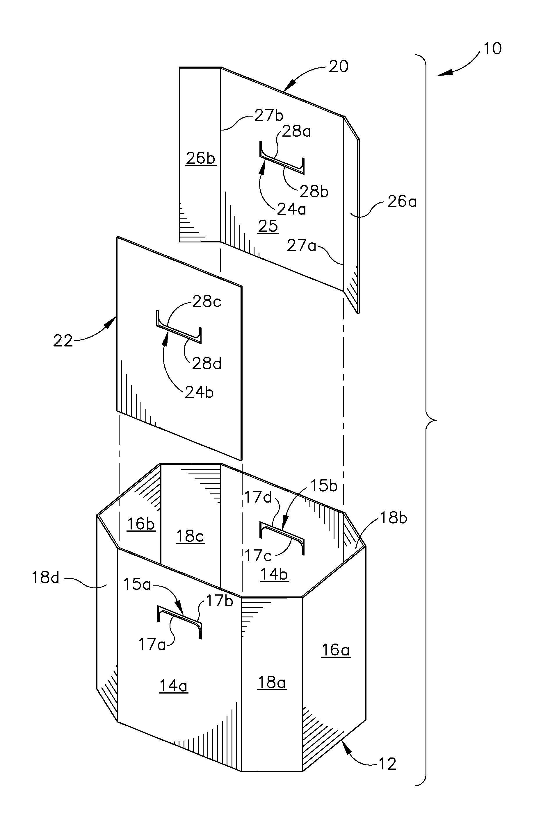
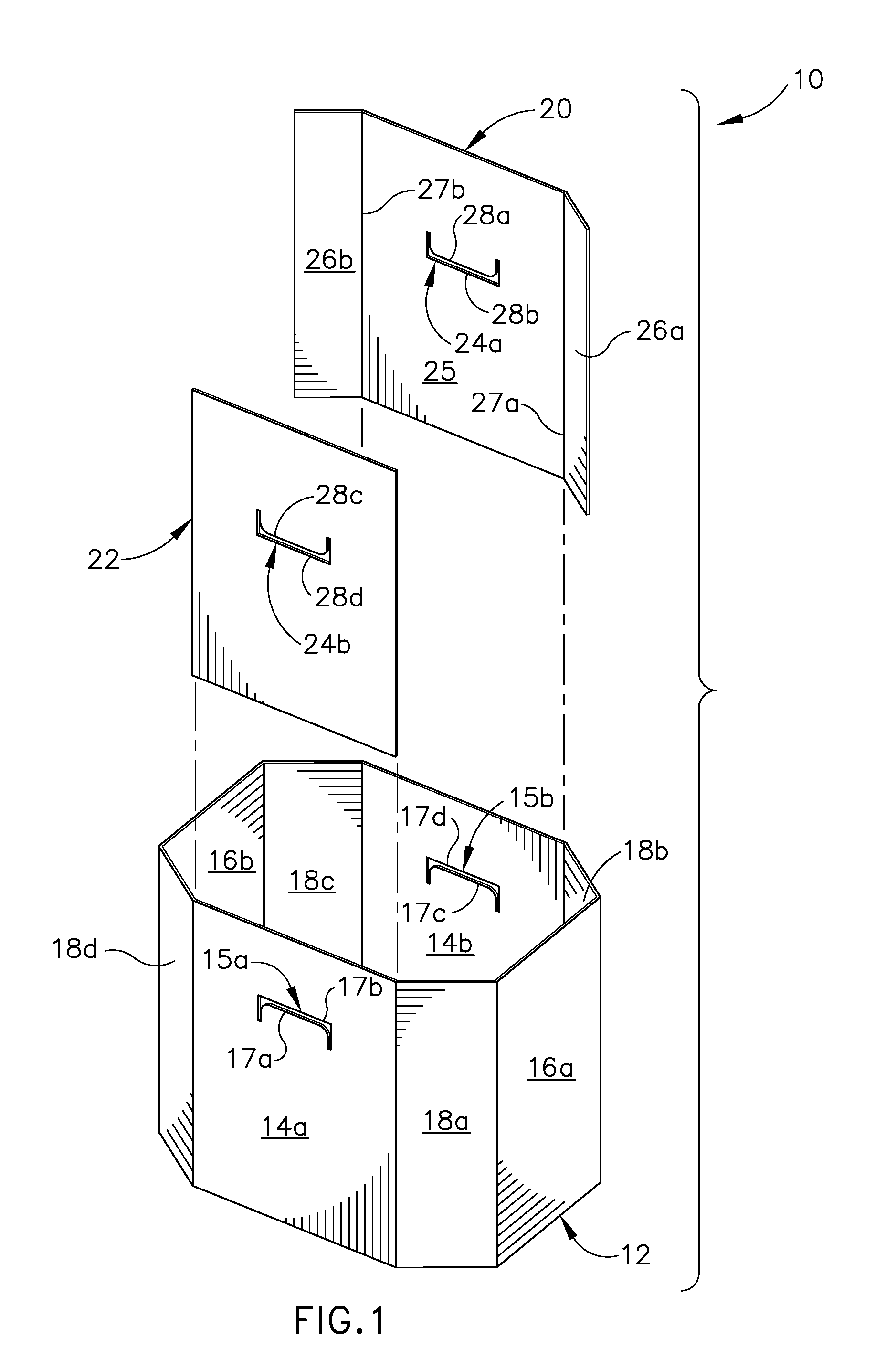
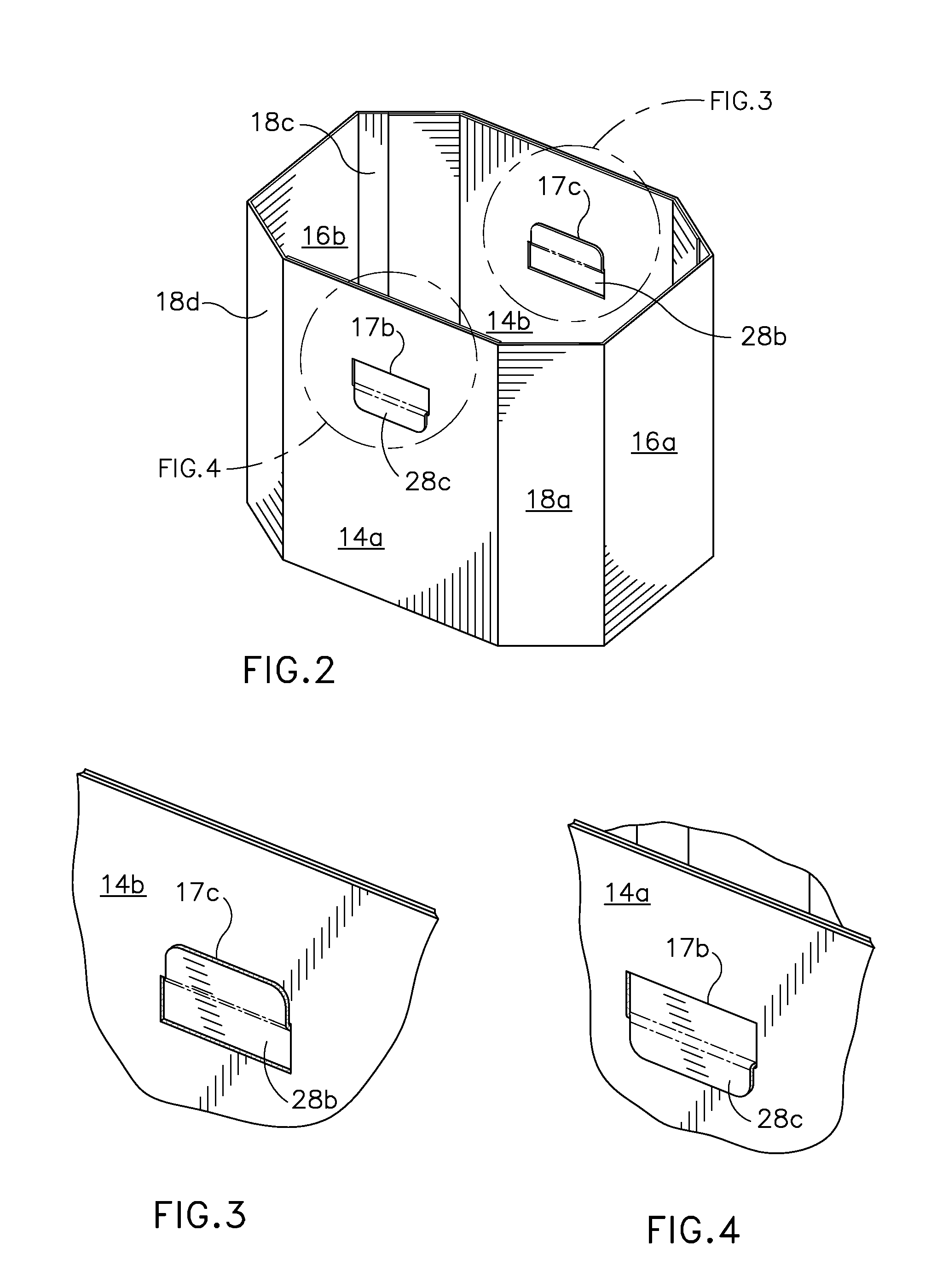
[0028]FIG. 1 is an exploded perspective view of a shipping container 10 having a body 11 and two self-locking support panels 20, 22 in a spaced relationship in accordance to the invention. The body 11 comprises a bottom wall 12, opposite parallel side walls 14a, 14b, opposite parallel end walls 16a, 16b and diagonal corner walls 18a, 18b, 18c, and 18d connecting the respective side walls 14a, 14b and respective end walls 16a, 16b at adjacent ends. Each of the respective side walls 14a 14b includes a respective first and second locking members 15a and 15b that are formed thereto above the central portion and they are substantially the same shape. The first locking member 15a includes a first locking tab 17a and a first U-shaped slot 17b. The first U-shaped slot 17b is formed by indentation of the first locking tab 17a toward the interior of the body 11. Similarly, the second locking member 15b includes a second locking tab 17c and a second U-shaped slot 17d which the second U-shaped ...

second embodiment

[0032]FIG. 6 is an exploded perspective view of a shipping container 40 having a body 42 and four self-locking support panel posts 44a, 44b, 44c, and 44d in a spaced relationship in accordance to the invention. The body 42 comprises a bottom wall 46 and four parallel side walls 48a, 48b, 48c, and 48d foldably joined with one another. Each of the respective side walls 48a, 48b, 48c, and 48d includes a pair of respective first locking members 50a, 50b, 50c, and 50d that are formed near side edge and above the central portion of each side wall and they are substantially the same shape. Each of the first pair of locking member 50b, 50c, and 50d includes respective a first locking tab 52c and a first U-shaped slot 52d, a first locking tab 52e and a first U-shaped slot 52f, a first locking tab 52g and a first U-shaped slot 52h. Each of the respective self-locking support panel posts 44a, 44b, 44c, and 44d is defined by a respective pair of panels 53a, 53b, 53c, and 53d foldably joined to ...

third embodiment

[0035]FIG. 11 is an exploded perspective view of a shipping container 60 having a body 62 and two self-locking support panels 64a, 64b in a spaced relationship in accordance to the invention. The body 62 comprises a bottom wall 66, opposite parallel side walls 68a, 68b, opposite parallel end walls 70a, 70b which are foldably joined to one another. Each of the respective end walls 70a, 70b includes a respective first and second locking members 72a and 72b that are formed thereto proximately on the central portion and they are substantially the same shape. The first locking member 72a includes a first locking tab 74a and a first U-shaped slot 74b. The first U-shaped slot 74b is formed by indentation of the first locking tab 74a toward the interior of the body 62. Similarly, the second locking member 72b includes a second locking tab 74c and a second U-shaped slot 74d which the second U-shaped slot 74d is formed by indentation of the second locking tab 74c toward the interior of the bo...


PUM


Abstract

A container comprises a body having a bottom wall, opposed side walls, and opposed end walls foldably joined with one another for holding and shipping different products contained therein. Each of the opposed side walls includes a respective first and second locking member. Two separate self-locking support panels each of which comprises a respective third and fourth locking members formed therein to be engaged with the corresponding first and second locking members in an overlapping relationship. Each of the first and second locking members is defined by a first locking tab and a first U-shaped slot that is formed by indentation of the first locking tab toward interior of the body of the container.

Description

FIELD OF THE INVENTION[0001]This invention relates generally to a shipping container constructed from a paperboard blank for holding a variety of articles and more particularly, to a shipping container having at least one separate support panel that significantly reduces bulging of the container.BACKGROUND OF THE INVENTION[0002]Numerous products are often packaged in large corrugated bulk containers. These products are generally small in size, packaged loosely, and are prone to shift around inside the container during transportation. The shifting of the products causes the sidewalls of the container to bulge; deforming the shape of the container and reducing the strength of the container to the point of failure. The bulging of the sidewalls deforms the container such that it is difficult to position the containers side by side in trucks and therefore reduces the number of containers that can be fit in a truck. Moreover, the bulging can also make it difficult to place the containers ...

Claims


Application Information

Patent Timeline
IPC IPC(8): B65D5/42
CPCB65D5/445
Inventor WISECARVER, MARK
Owner INT PAPER CO
Why Eureka
Try Eureka