Steering column device

a steering column and device technology, applied in the direction of steering columns, steering parts, vehicle components, etc., can solve the problems of increasing weight, reducing cost, and reducing quality control for welding, so as to improve flexural rigidity and resistance to vibration properties, reduce natural vibration frequency, and reduce product cost

Inactive Publication Date: 2006-03-16
NSK LTD
View PDF1 Cites 7 Cited by
  • Summary
  • Abstract
  • Description
  • Claims
  • Application Information

AI Technical Summary

Benefits of technology

[0026] According to the present invention, it is possible to eliminate steps for fabricating a distance bracket and a lower bracket, to be prepared separately, a welding step for fixedly positioning those elements onto the column body, and a quality control therefor, whereby a product cost can be reduced. Furthermore, in this steering column device, a swelled shell part with a deformed cross section is provided on the column body, thereby improving flexural rigidity and resistance to vibration property in the longitudinal direction. Further in a type of steering column device having a steering lock unit being mounted on the upper portion thereof, a reduction of natural vibration frequency, which is relatively caused by the mass of the steering lock unit, can be suppressed by providing the swelled shell part, whereby it is possible for the steering column device or the column body to become resistant to resonance, without increasing weight of the column body, and thus a deterioration in steering operability can be prevented.

Problems solved by technology

Therefore, not only steps for making the distance bracket 21d and the lower bracket 22t are respectively required, as well as a welding step and the like for fixedly positioning these elements onto the column body, but also quality control for welding is a significant issue, and thus cost reduction has not been achieved as intended.
However, there is a problem that an increase in weight cannot be avoided.
If a tubular member is employed as it is for the column device like conventional manner, it is substantially difficult to vary the flexural rigidity and directionality in vibration level.
Therefore, a possible countermeasure is only to make the wall thicker, thereby rendering the flexural rigidity and vibration property in horizontal direction also unnecessarily enhanced, even if it is not a significant requirement.
Therefore, the above problem becomes further critical.

Method used


Image

  • Steering column device
  • Steering column device
  • Steering column device

Examples


first embodiment

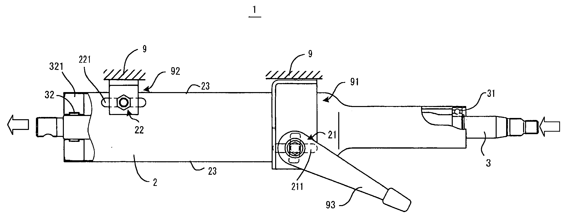
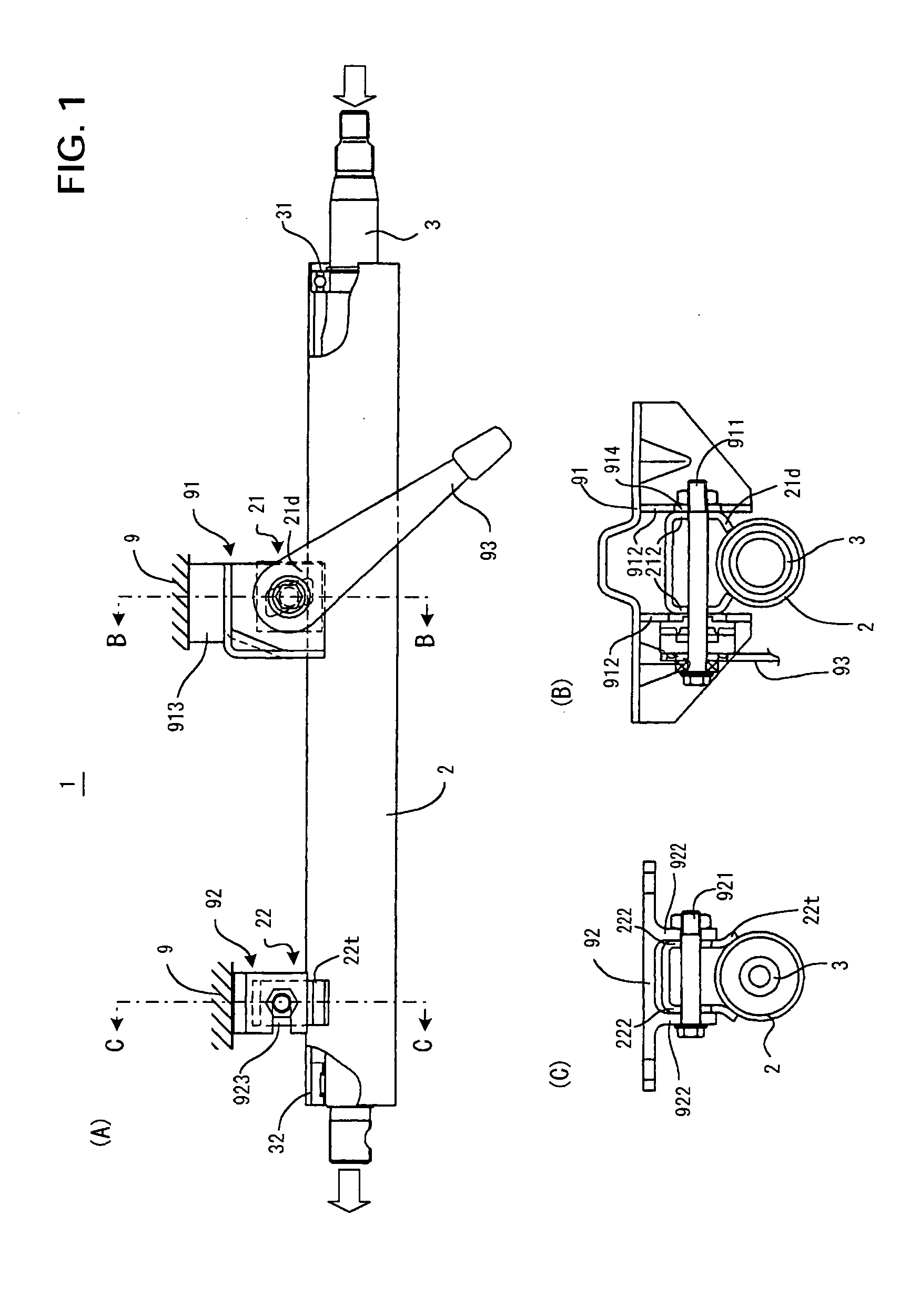
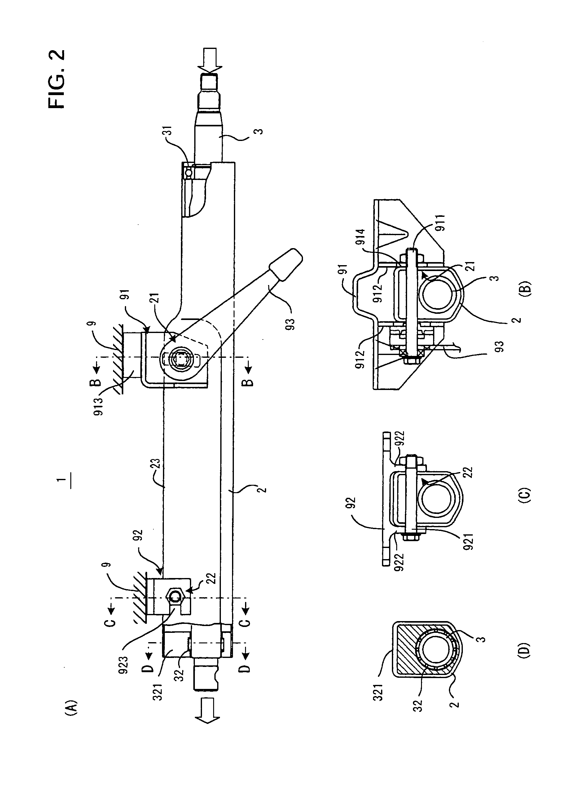
[0038] The steering column device 1 includes a tubular shaped column body 2 having a swelled shell part 23 and a steering shaft 3 which penetrates inside the column body 2. The steering shaft 3 is rotatably supported by an upper bearing 31 and a lower bearing 32, which are respectively provided at both ends of the column body 2. A steering wheel, not illustrated is coupled with one end thereof (in the right side in FIG. 2(A)), and the other end thereof (in the left side in FIG. 2(A)) is connected to a vehicle steering mechanism via an intermediate shaft.

[0039] The swelled shell part 23 is provided with an upper body mounting part 21 and a lower body mounting part 22, respectively on the two points along the longitudinal direction of the column body 2. On the vehicle body 9 side, a vehicle body side upper mounting part 91 and a vehicle body side lower mounting part 92 are respectively fixed on the positions corresponding to the upper body mounting part 21 and the lower body mounting...

second embodiment

[0047]FIG. 5 is an explanatory diagram for explaining the steering column device 1 according to the second embodiment of the present invention. In this figure, since the upper body mounting part 21, the lower body mounting part 22 and the cross section in proximity to the lower bearing 32 are similar to those in FIG. 2(B), FIG. 2(C) and FIG. 2(D), those figures can be referred to, if necessary.

[0048] Since the steering column device 1 as a whole has a structure in common with the first embodiment, the explanation thereof may be referred to. The swelled shell part 23 of the column body 2 in this example comprises separated two parts, an upper swelled shell part 231 including a portion in the proximity of the upper body mounting part 21, and a lower swelled shell part 232 including a portion in the proximity of the lower body mounting part 22, in such a manner as placing a constriction 233 therebetween. This constriction 233 can be formed in any shape freely to some extent, and thus r...

third embodiment

[0049]FIG. 6 is an explanatory diagram for explaining the steering column device 1 according to the third embodiment of the present invention.

[0050] In this steering column device 1, the swelled shell part 23 of the column body 2 is swelled symmetrically, placing the steering shaft 3 therebetween. Further, an upper body mounting part 21 is provided on the downside of the swelled shell part 23 as shown in FIG. 6(A). In some vehicle structures, it is possible to give a degree of flexibility in arrangement of the steering column device 1 by providing the upper body mounting part 21 on the downside as shown in this example. Furthermore, the bearing spacer 321 is also symmetrically provided with respect to the lower bearing 32.

[0051] Since the column body 2 is vertically symmetrical, a flexure and the like hardly occur when a diameter of the tubular member is expanded, thereby bringing certain advantages such as facilitating a processing step.

[0052]FIG. 7 is a side view showing a vari...


PUM


Abstract

A steering column device (1), comprising a column body (2) having a swelled shell part (23) in deformed section swelled in the side direction of a steering shaft (3) beyond the portion of thereof where an upper bearing (31) is installed and having opposed walls parallel with each other, wherein a lower body mounting part (22) and an upper body mounting part (21) are formed in the swelled shell part (23), whereby a distance bracket and a lower bracket must not be prepared and fixedly positioned on the column body.

Description

TECHNICAL FIELD [0001] The present invention relates to a steering column device for a vehicle. BACKGROUND ART [0002] A steering column device is placed in a space for a driver's seat, between a meter panel provided above and a room for driver's knees provided below. The steering column device is equipped with a steering shaft, a steering wheel being mounted on the top end of the steering shaft and the lower end thereof being coupled to a vehicle body steering mechanism for controlling orientations of front wheels. [0003]FIG. 1 shows a conventional steering column device 1. Generally, this steering column device 1 includes a tubular shaped column body 2 and a steering shaft 3 which penetrates inside the column body 2. The steering shaft 3 is rotatably supported by an upper bearing 31 and a lower bearing 32, which are respectively provided in proximity to both ends of the column body 2. A steering wheel, not illustrated, is coupled with one end thereof (in the right side in FIG. 1(A)...

Claims


Application Information

Patent Timeline
Patent Type & Authority Applications(United States)
IPC IPC(8): B62D1/18B62D1/16B62D1/184B62D1/189
CPCB62D1/16B62D1/189B62D1/184
Inventor SAWADA, NAOKINISHIOKA, MASAKISATO, KENJI
Owner NSK LTD
Why Eureka
Try Eureka