Car body structure

a car body and arrangement technology, applied in the direction of railway bodies, railway roofs, window arrangements, etc., can solve problems such as inapplicability, and achieve the effects of suppressing bending vibration, improving flexural rigidity, and good riding quality

Inactive Publication Date: 2008-10-21
HITACHI LTD
View PDF11 Cites 6 Cited by
  • Summary
  • Abstract
  • Description
  • Claims
  • Application Information

AI Technical Summary

Benefits of technology

[0009]The object of the present invention is to provide a railway car body structure with a good riding quality by suppressing the bending vibration in the vertical direction of the railway car body, which is provided by a car body structure having an improved flexural rigidity and minimum mass increase.
[0010]The present object is achieved by increasing the rigidity of the roof construction at the longitudinal center portion of the car body structure than the rigidity of the roof construction at other portions (by increasing the thickness or the modulus of longitudinal elasticity of the material), or by increasing the rigidity of the lower portion of the side constructions at the longitudinal center portion of the car body structure than the rigidity of the lower portion of the side constructions at other portions.

Problems solved by technology

However, this is not practical since it causes interference with the surrounding infrastructure facilities.

Method used


Image

  • Car body structure
  • Car body structure
  • Car body structure

Examples


embodiment 1

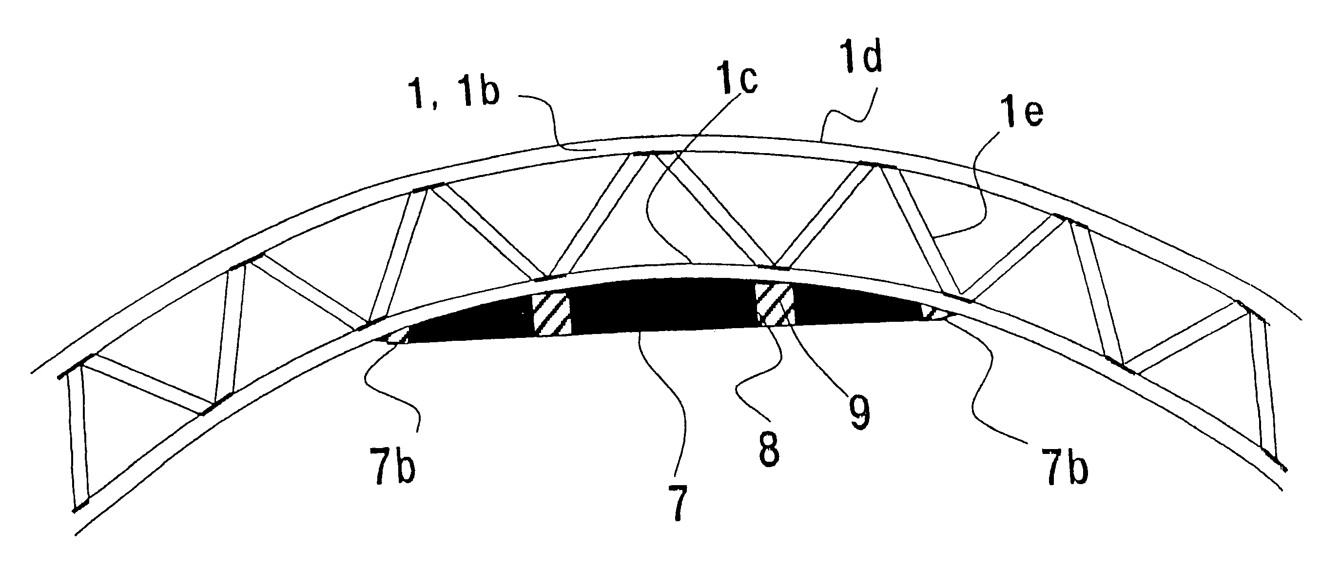
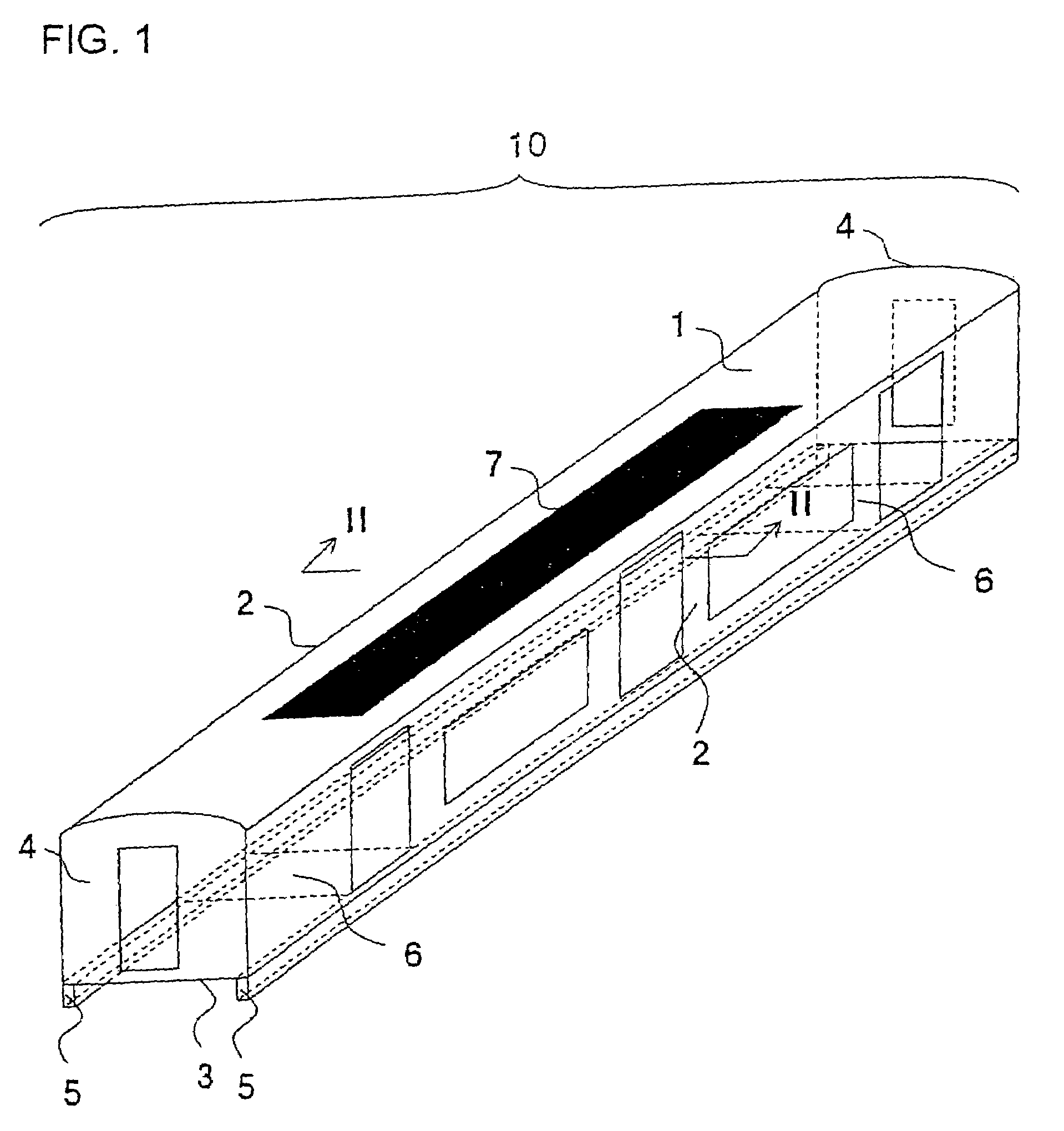
[0032]The first embodiment of the present invention is described with reference to FIGS. 1 and 2. A railway car body structure 10 is composed of a roof construction 1 constituting the upper face thereof, two side constructions 2 constituting the side walls thereof, an underframe 3 constituting the bottom face thereof, and two end constructions 4 constituting the end faces thereof. Side sills 5 are disposed at the lower portion of the side constructions 2. Body bolsters 6 are disposed on the under frame 3 for connecting the underframe 3 and a running gear (not shown).

[0033]The roof construction 1, the side constructions 2, the underframe 3 and the end constructions 4 are each formed by welding plural extrusions. The extrusions used for forming the roof construction 1, the side constructions 2 and the underframe 3 are hollow extrusions made of aluminum alloy, and their directions of extrusion correspond to the longitudinal direction of the railway car body structure 10. The extrusions...

embodiment 2

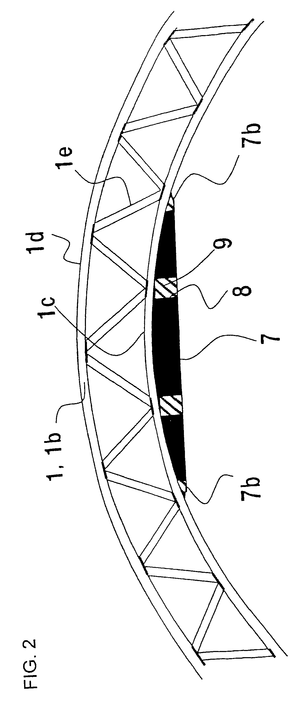
[0048]The second embodiment of the present invention will be described with reference to FIG. 3. FIG. 3 illustrates an example in which a reinforcing plate 7 having a uniform thickness is provided. The reinforcing plate 7 is bent via machining. The fixing structure of the reinforcing plate 7 is the same as that of FIG. 2.

[0049]According to this embodiment, the machining of the side of the reinforcing plate 7 facing the outer side of the car becomes unnecessary, by which the costs can be cut down.

embodiment 3

[0050]The third embodiment of the present invention will be described with reference to FIGS. 4, 5 and 6. This embodiment does not utilize the reinforcing plate 7.

[0051]The thickness of the face plate 1c of the hollow extrusion constituting the roof construction 1 facing the inner side of the car body and the face plate 1d facing the outer side thereof at the longitudinal center portion of the roof construction 1 (portion V of the drawing) is greater than the thickness of the face plates 1c and 1d of the hollow extrusion at the longitudinal ends (portions VI) thereof.

[0052]According to this embodiment, the reinforcing plate 7 becomes unnecessary, which is advantageous from the viewpoint of space, number of components, welding costs and so on. Further, it should be noted that the frames illustrated by the dashed lines between portions IV and portion V are for indicating sections, and no such frame is actually formed.


PUM


Abstract

The invention provides a railway car with superior riding quality by improving the flexural rigidity of the car body structure while suppressing increase of body structure mass. A reinforcing plate 7 is attached to a roof construction 1 on the side facing an inner side of the car body at a longitudinal center portion of a railway car body structure 10 composed of a roof construction 1, a side construction 2, an underframe 3 and an end construction 4. The range in which the reinforcing plate 7 is adhered in the longitudinal direction of the railway car body structure 10 is between two body bolsters 6, and the range in which the plate 7 is adhered in the horizontal direction of the roof construction 1 is approximately half the length of the roof construction 1 in the horizontal direction. The thickness of the reinforcing plate 7 is increased gradually as the height of the roof construction 1 in the vertical direction increases. According to this arrangement, the deformation of the roof construction 1 at the longitudinal center portion of the railway car body structure 10, which is excessive without the present arrangement, is suppressed, and the flexural rigidity of the railway car body structure 10 is effectively improved. In other words, the bending vibration of the railway car body in the vertical direction can be suppressed, and a superior riding quality is provided.

Description

[0001]The present application is based on and claims priority of Japanese patent application No. 2005-109591 filed on Apr. 6, 2005, the entire contents of which are hereby incorporated by reference.BACKGROUND OF THE INVENTION[0002]1. Field of the Invention[0003]The present invention relates to an arrangement of a car body structure of a railway car, a monorail car or the like.[0004]2. Description of the Related Art[0005]A railway car body structure is composed of a roof construction constituting the upper face thereof, two side constructions constituting the side walls thereof, an underframe constituting the lower face thereof, and two end constructions constituting the ends thereof. In recent years, in order to mainly reduce the weight of the car body and to improve the productivity thereof, hollow extrusions made of aluminum alloy are used to construct the roof construction, the side constructions and the underframe, and extrusions with ribs made of aluminum alloy are used to cons...

Claims


Application Information

Patent Timeline
Patent Type & Authority Patents(United States)
IPC IPC(8): B61D17/00
CPCB61D17/041B61D17/10B61D17/12B61D17/00
Inventor NAKAMURA, HIDEYUKIFURUKAWA, TAKASHIYOSHIDA, TAKASHI
Owner HITACHI LTD
Why Eureka
Try Eureka