

Pneumatic valve control mechanism
A technology of pneumatic valves and control mechanisms, applied in engine components, valve details, multi-port valves, etc., can solve the problems of loss of complete sealing, rising use and maintenance costs, short service life of sealing rings, etc., to reduce installation space, use Long life and stable sealing performance
- Summary
- Abstract
- Description
- Claims
- Application Information
AI Technical Summary
Problems solved by technology
Method used
Image

Examples
Embodiment Construction
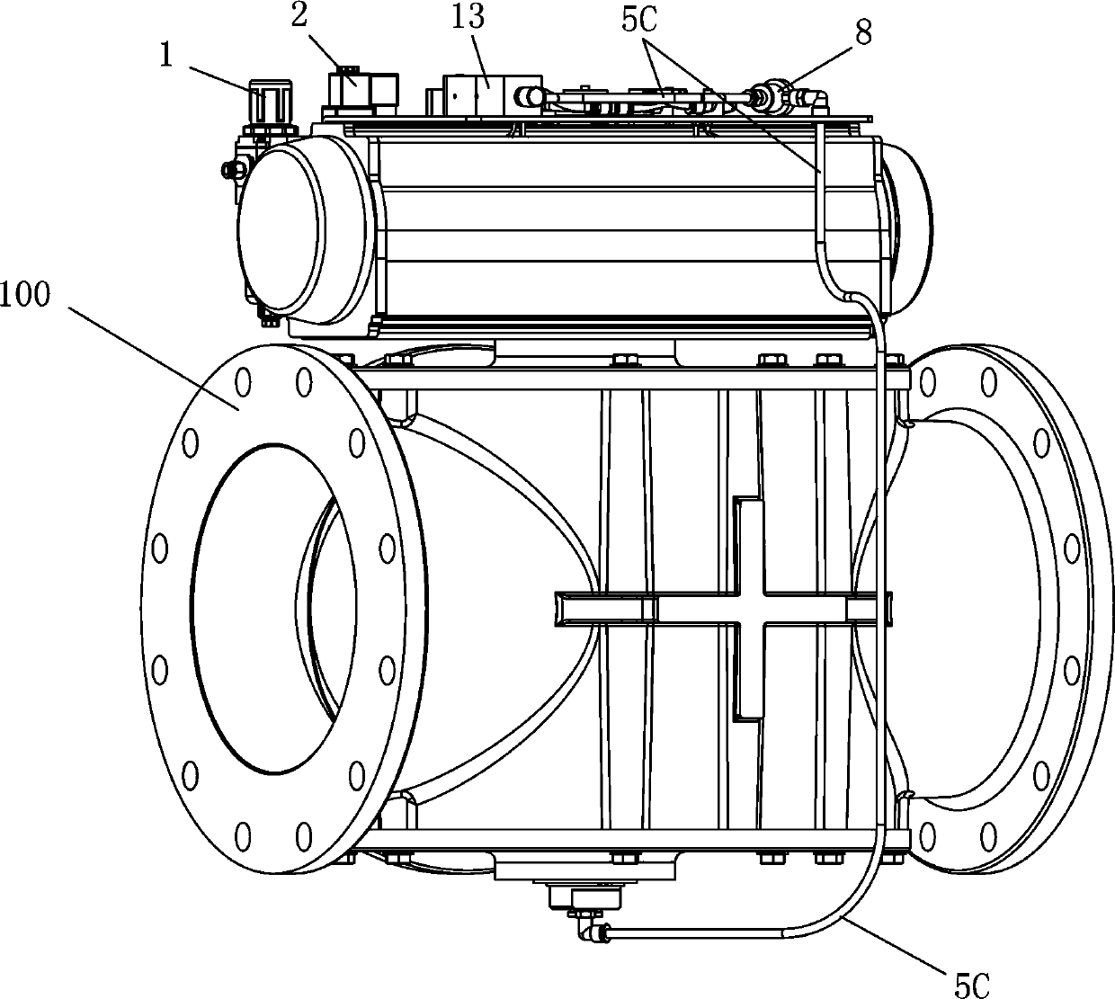
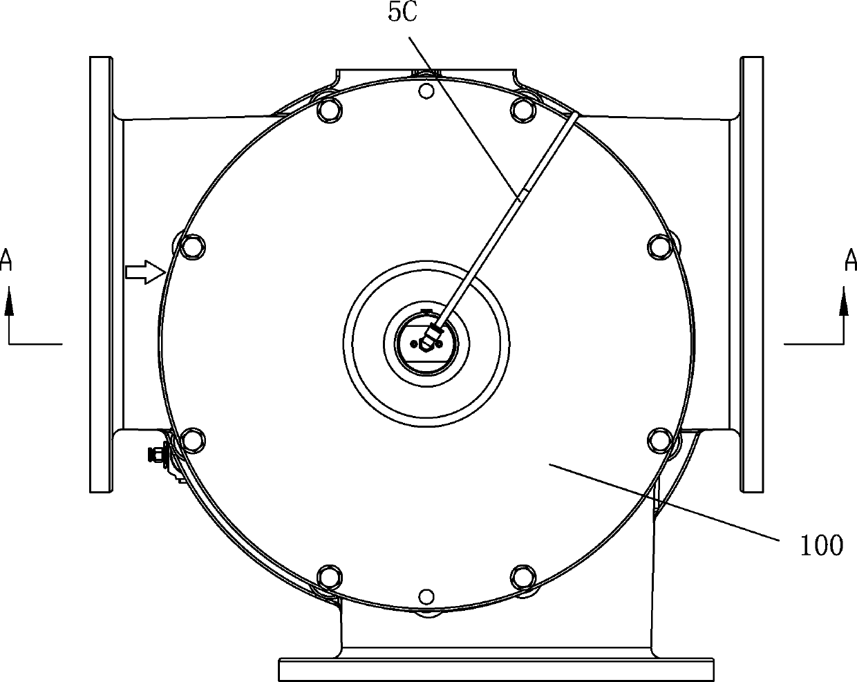
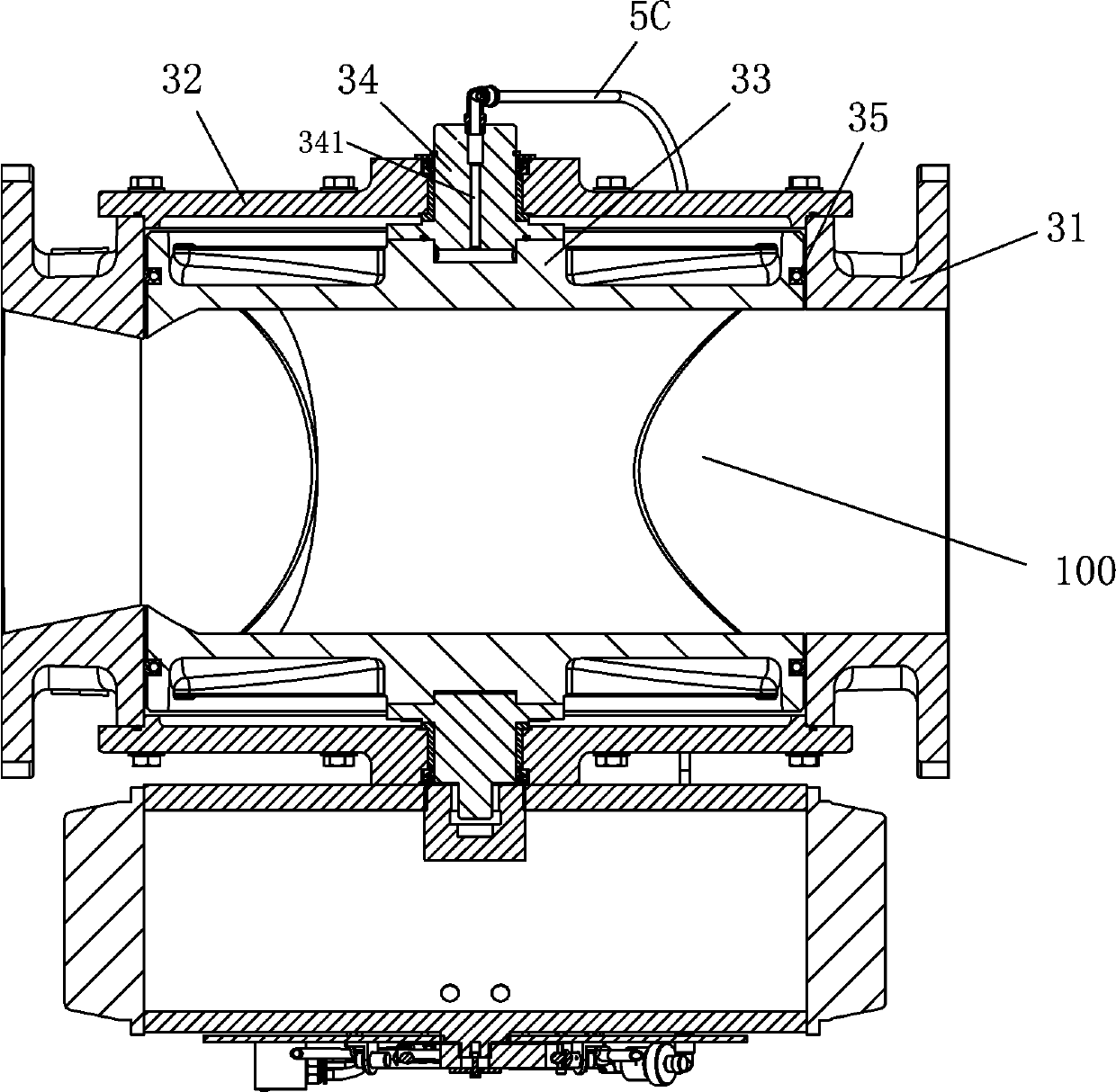
[0028] see Figure 1 to Figure 8 , the pneumatic valve control mechanism of the present invention, the pneumatic valve 100 includes: a valve body 31 and its upper valve cover 32, the valve body 31 is a three-way structure; a valve core 33 arranged in the valve body 31; A valve shaft 34 connected to the spool 33; the spool 33 is provided with a radially through channel; it includes a rotating cylinder 7, a cylinder driving actuator, a sealing control mechanism, and a spool action position detection mechanism;
[0029] The outer walls of the two ports of the corresponding passage of the spool 33 are respectively provided with a sealing groove 331 along the circumferential direction, and an inflatable sealing ring 35 is respectively arranged in the two sealing grooves 331; The spool inlet passage 332 communicated with the groove 331; the valve shaft inlet passage 341 is arranged axially in the valve shaft 34, and the valve shaft inlet passage 341 communicates with the valve core ...
PUM
 Abstract
Description
Claims
Application Information