
Environment detection device for industrial production plant concentration area

A technology for environmental detection and industrial production. It is applied in measurement devices, variable measurement arrangements, instruments, etc. It can solve the problems of illegal emission of polluting gases and cannot be monitored at any time, and achieve the effect of saving energy.

Inactive Publication Date: 2019-03-29
江苏绿途环保科技有限公司
View PDF6 Cites 0 Cited by
  • Summary
  • Abstract
  • Description
  • Claims
  • Application Information

AI Technical Summary

Problems solved by technology

[0002] In order to solve the problem of illegal emission of polluting gases in the factory, the environmental protection department regularly visits the factory to detect the composition of the exhaust gas. However, this method cannot be monitored at any time to know in real time whether the factory exhaust gas is in violation of regulations.

Method used


Image

  • Environment detection device for industrial production plant concentration area
  • Environment detection device for industrial production plant concentration area
  • Environment detection device for industrial production plant concentration area

Examples


Embodiment Construction

[0025] The following will clearly and completely describe the technical solutions in the embodiments of the present invention with reference to the accompanying drawings in the embodiments of the present invention. Obviously, the described embodiments are only some, not all, embodiments of the present invention.

[0026] In describing the present invention, it should be understood that the terms "upper", "lower", "front", "rear", "left", "right", "top", "bottom", "inner", " The orientation or positional relationship indicated by "outside", etc. is based on the orientation or positional relationship shown in the drawings, and is only for the convenience of describing the present invention and simplifying the description, rather than indicating or implying that the referred device or element must have a specific orientation, so as to Specific orientation configurations and operations, therefore, are not to be construed as limitations on the invention.

[0027] refer to Figure ...


PUM


Abstract

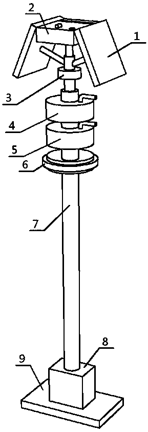
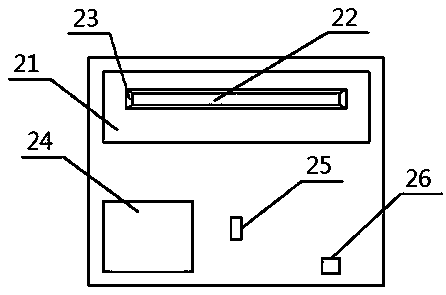
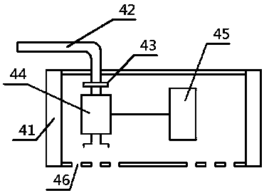
The invention discloses an environment detection device for an industrial production plant concentration area, which comprises solar panels, an air projection device, a device processor, a dust concentration detection device, a harmful gas detection device and a noise detection device, wherein two sides of the top of one end of a pillar are provided with the solar panels; the top of one end of thepillar is provided with the air projection device; the bottom side of one end of the air projection device is connected with the device processor; one end, far away from the air projection device, ofthe device processor is provided with the dust concentration detection device; the bottom side of one end of the dust concentration detection device is provided with the harmful gas detection device;one end, far away from the dust concentration detection device, of the harmful gas detection device is provided with the noise detection device; the bottom part of one end of the pillar is provided with a battery; and the bottom of the battery is provided with a base. Through arranging a plurality of detection devices around the plant area to monitor the environment state around the plant area inreal time, the effects of enabling an environmental protection department to perform timely monitoring and processing can be achieved.

Description

technical field [0001] The invention relates to the field of environment detection, in particular to an environment detection device for concentrated areas of industrial production factories. Background technique [0002] In order to solve the problem of illegal emission of polluting gases in the factory, the environmental protection department regularly visits the factory to detect the composition of the emission gas. Contents of the invention [0003] The object of the present invention is to provide an environment detection device for concentrated areas of industrial production factories in order to overcome the above defects. [0004] In order to achieve the above object, the present invention adopts the following technical solutions: [0005] An environmental detection device for concentrated areas of industrial production factories, which includes solar panels, air projection devices, equipment processors, dust concentration detection equipment, harmful gas detectio...

Claims


Application Information

Patent Timeline
IPC IPC(8): G01D21/02G01D1/18
CPCG01D1/18G01D21/02
Inventor 李奎
Owner 江苏绿途环保科技有限公司
Learn More