A pointed holographic antenna

A holographic antenna, sharp-angle technology, applied in the direction of the antenna, the structure connection of the antenna grounding switch, the structure form of the radiating element, etc., can solve the problems of phase difference, affecting the radiation pattern generation efficiency, electromagnetic wave radiation efficiency, etc., so as to reduce the phase difference and improve the Generation efficiency, electromagnetic wave radiation efficiency, and effect of reducing adverse effects

Active Publication Date: 2021-06-01
XIAN CREATION KEJI CO LTD
View PDF10 Cites 0 Cited by
  • Summary
  • Abstract
  • Description
  • Claims
  • Application Information

AI Technical Summary

Problems solved by technology

[0004] However, due to the different distances that the electromagnetic wave propagates in the waveguide horn part, a phase difference may occur, which in turn affects the generation efficiency of the radiation pattern and the radiation efficiency of the electromagnetic wave

Method used


Image

  • A pointed holographic antenna
  • A pointed holographic antenna
  • A pointed holographic antenna

Examples


Embodiment 1

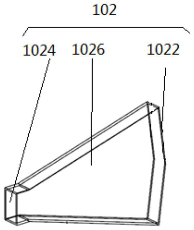
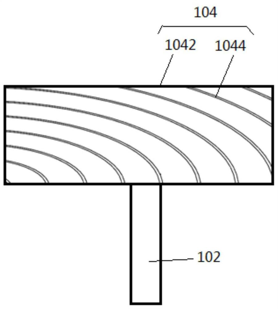
[0021] See figure 1 and image 3 , figure 1 A schematic structural diagram of a pointed holographic antenna provided by an embodiment of the present invention, image 3 A schematic structural diagram of another pointed-shaped holographic antenna provided by an embodiment of the present invention.

[0022] Such as figure 1 and image 3 As shown, the holographic antenna includes: a waveguide horn part 102 and a holographic structure part 104, and the horn port 1022 of the waveguide horn part 102 is pointed.

[0023] Specifically, the holographic antenna includes: the waveguide horn part 102 includes a rectangular waveguide feeding cavity 1024 and a horn radiation cavity 1026 , the rectangular waveguide feeding cavity 1024 is connected with the horn radiation cavity 1026 to form the waveguide horn part 102 . In the waveguide horn part 102 , the open surface on the side of the horn radiation cavity 1026 is the horn port 1022 .

[0024] understandable, such as figure 1 As sh...

Embodiment 2

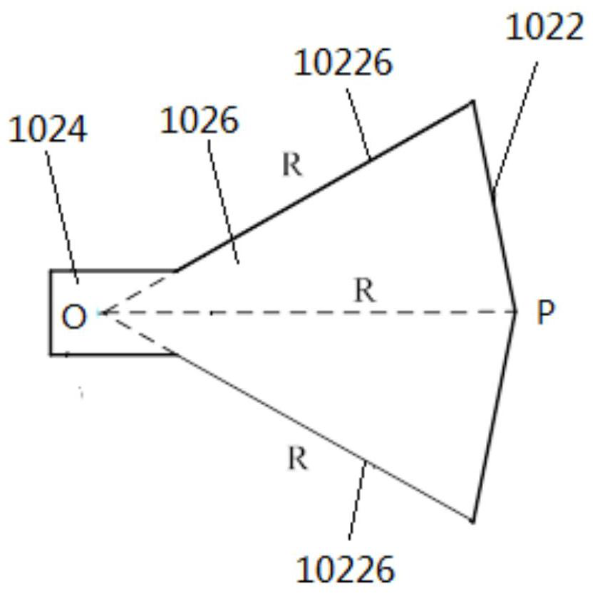
[0030] See figure 2 , figure 2 A schematic structural diagram of another pointed-shaped holographic antenna provided by an embodiment of the present invention. exist figure 2 , the position of the apex of the pointed shape is determined by a preset origin and a preset side length, wherein the preset origin is the extension line of the two horn radiation sides 10226 of the waveguide horn part 102 For the intersection point, the preset side length is the distance from the preset origin, along the horn radiation side 10226 , to the horn port 1022 .

[0031] Specifically, such as figure 2 As shown, the preset origin is point O, the preset side length is R, and the vertex of the pointed shape is P. The preset origin can be the intersection point of extension lines of the horn radiation side 10226 of the waveguide horn part 102 , and the preset side length is the distance from the origin, along the horn radiation side 10226 , to the horn port 1022 . At the same time, the di...


PUM


Abstract

The present invention relates to a pointed-shaped holographic antenna, which includes: a waveguide horn part 102; a horn port 1022 of the waveguide horn part 102 is pointed-shaped. The application of the embodiment of the present invention can improve the generation efficiency of the radiation pattern and the radiation efficiency of electromagnetic waves.

Description

technical field [0001] The invention belongs to the technical field of antennas, and in particular relates to a pointed holographic antenna. Background technique [0002] With the development of antenna technology, holographic antenna came into being. Compared with the traditional reflector antenna, the holographic antenna can obtain the required radiation characteristics by changing the holographic structural components according to the application environment and actual needs, without the need for a fixed contour structure, and has better concealment. [0003] Currently, holographic antennas may include waveguide horn components and holographic structural components. The electromagnetic wave radiated by the waveguide horn part can form a radiation pattern through the holographic structure part. [0004] However, due to the different propagation distances of the electromagnetic wave in the waveguide horn part, a phase difference may occur, thereby affecting the generation...

Claims


Application Information

Patent Timeline
Patent Type & Authority Patents(China)
IPC IPC(8): H01Q19/06H01Q13/02H01Q1/36H01Q1/50H01Q15/02
CPCH01Q1/36H01Q1/50H01Q13/02H01Q15/02H01Q19/067
Inventor 乔丽萍祖缘杭联茂李鹏李丽
Owner XIAN CREATION KEJI CO LTD
Why Eureka
Try Eureka