
Short circuit protection circuit for four-leg H-bridge driver chip

A technology of short-circuit protection circuit and bridge drive circuit, which is applied to emergency protection circuit devices, overcurrent-responsive protection, electrical components, etc., and can solve power consumption burnout, chip damage, pin PIN3 and pin GND short circuit, etc. problems, to achieve the effect of preventing excessive short-circuit current

Inactive Publication Date: 2019-03-29
SHANGHAI ORIENT CHIP TECH CO LTD
View PDF0 Cites 1 Cited by
  • Summary
  • Abstract
  • Description
  • Claims
  • Application Information

AI Technical Summary

Problems solved by technology

If there is a short circuit, the chip will burn out due to excessive power consumption after the chip is powered on.
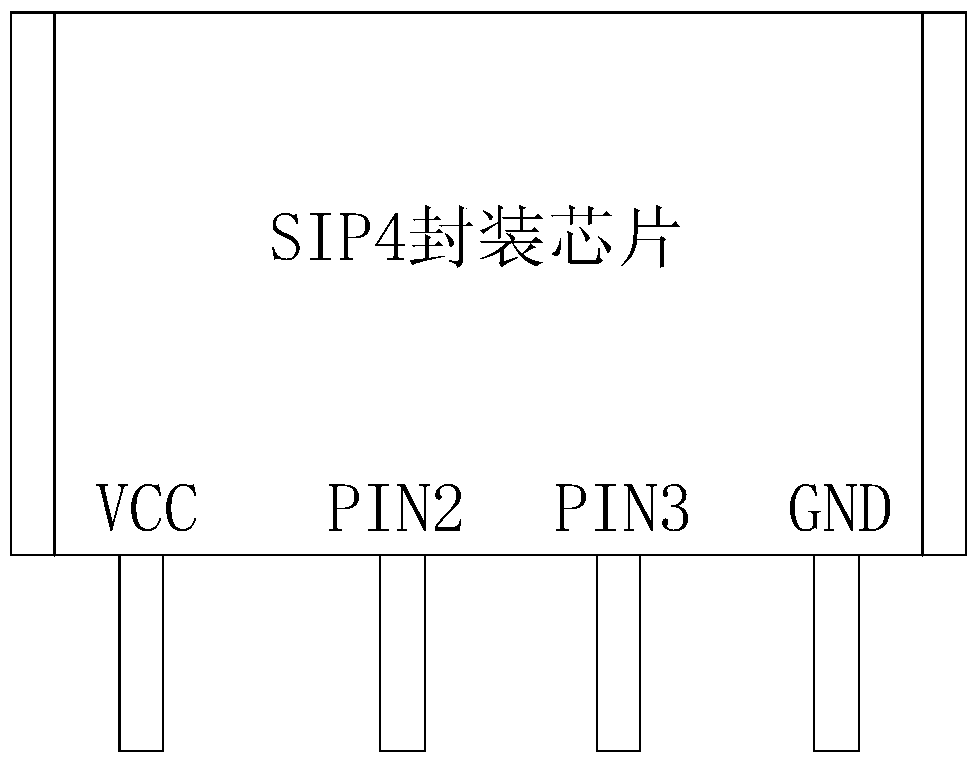
[0003] by figure 1 Take the SIP4 package chip shown as an example, because the distance between two adjacent pins is small, when the whole machine is soldered, it is easy to have a short circuit between pin PIN2 and pin VCC, a short circuit between pin PIN2 and pin PIN3, and a short circuit between pin PIN2 and pin PIN3. Short circuit between pin PIN3 and pin GND
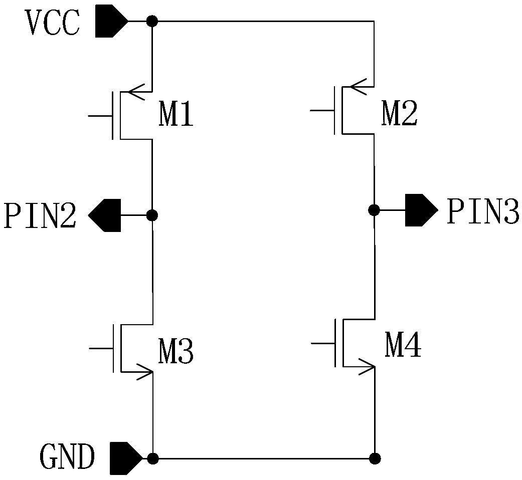
If the above-mentioned short-circuit situation occurs, when the chip is working, its internal H-bridge drive circuit (such as figure 2 Shown) there will be a large current path causing the chip to burn
[0004] Specifically, in the figure 2 In the H-bridge drive circuit of the H-bridge drive chip shown, if the pin PIN2 is short-circuited to the pin VCC, when the drive tube M3 is turned on, there will be a large current path from the power supply to the ground, causing damage to the chip; if the pin PIN3 is short-circuited to GND, when the drive tube M2 is turned on, there will be a large current path from the power supply to the ground, causing damage to the chip; if the pin PIN2 is short-circuited to the pin PIN3, when the drive tube M1 and the drive tube M4 are turned on , the driving tube M1 and the driving tube M4 will have a large current at the same time, causing damage to the chip; When the drive tube in the drive tube is turned on normally, it will cause the chip to burn out

Method used


Image

  • Short circuit protection circuit for four-leg H-bridge driver chip
  • Short circuit protection circuit for four-leg H-bridge driver chip
  • Short circuit protection circuit for four-leg H-bridge driver chip

Examples


Embodiment Construction

[0054]Below in conjunction with the drawings, preferred embodiments of the present invention are given and described in detail.

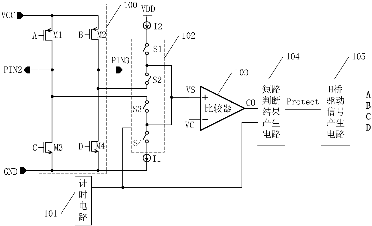
[0055] like Figure 3-5 As shown, the present invention is a short-circuit protection circuit for a four-pin H-bridge drive chip. The four-pin H-bridge drive chip has pins VCC, PIN2, PIN3 and GND. The short-circuit protection circuit includes: an H-bridge drive circuit 100, The timing circuit 101 is serially connected in series with the internal power supply VDD of the chip (VDD can be at the same level as the voltage VCC (VCC is the pin voltage of the chip’s external power supply pin), or it can be an internal voltage VCC generated by the internal step-down regulator circuit of the chip. power supply voltage) and the second current bias source I2 between the pin GND, the switch circuit 102 and the first current bias source I1, the comparator 103 connected to the switch circuit 102 in turn, the short circuit judgment result generating circuit 104 an...


PUM


Abstract

The invention relates to a short circuit protection circuit for a four-leg H-bridge driver chip. The short circuit protection circuit includes an H-bridge driving circuit, a timing circuit, and a switching circuit, a comparator, a short-circuit judgement result generating circuit and an H-bridge driving signal generating circuit that are sequentially connected to the H-bridge driving circuit, wherein the timing circuit is further connected to the short-circuit judgement result generating circuit, the switching circuit is connected between an internal power supply and a pin GND of a chip, and the H-bridge driving signal generating circuit is further connected to the H-bridge driving circuit. The short circuit protection circuit detects whether there is a short circuit condition between twoadjacent pins before the chip works normally, and if there is a short circuit, all H-bridge driving tubes can be turned off by generation of a protection signal, thereby preventing the chip from beingburnt out due to excessive current of the short circuit, and thus, short circuit protection of the four-leg H-bridge driver chip is achieved.

Description

technical field [0001] The invention relates to a protection circuit, in particular to a short-circuit protection circuit for a four-pin H-bridge drive chip. Background technique [0002] H-bridge driver chips are widely used in brushless DC motors. Because many manufacturers have limited technology and equipment, short circuits between adjacent pins often occur when chips are soldered. If there is a short circuit, the chip will burn out due to excessive power consumption after the chip is powered on. [0003] by figure 1 Take the SIP4 package chip shown as an example, because the distance between two adjacent pins is small, when the whole machine is soldered, it is easy to have a short circuit between pin PIN2 and pin VCC, a short circuit between pin PIN2 and pin PIN3, and a short circuit between pin PIN2 and pin PIN3. Pin PIN3 and pin GND are short-circuited. If the above-mentioned short-circuit situation occurs, when the chip is working, its internal H-bridge drive cir...

Claims


Application Information

Patent Timeline
IPC IPC(8): H02H7/20H02H3/08
CPCH02H3/08H02H7/20
Inventor 不公告发明人
Owner SHANGHAI ORIENT CHIP TECH CO LTD
Learn More