
Output ground short circuit protection circuit of frequency converter

A short circuit to ground and protection circuit technology, applied in emergency protection circuit devices, electrical components, etc., can solve problems such as large output current, short circuit of frequency converter, and lower insulation level, and achieve the effect of simple structure and avoiding excessive short circuit current

Pending Publication Date: 2018-11-23
深圳市默贝克驱动技术有限公司
View PDF0 Cites 0 Cited by
  • Summary
  • Abstract
  • Description
  • Claims
  • Application Information

AI Technical Summary

Problems solved by technology

With the long-term high-temperature use of the motor, the coil in the motor or the power line of the motor will continue to age, and the insulation level will gradually decrease and be broken down, causing the output of the inverter to be short-circuited to the ground. If the output of the inverter is not properly protected, the inverter will be damaged.
At present, domestic inverters rely more on the output-to-ground short-circuit protection of the inverter itself, or rely on the output Hall current sensor or drive optocoupler such as APCL330 and other devices with VCE detection for protection. The above two detection methods have their own defects. The response time of the sensor is relatively slow, and the optocoupler with VCE detection needs a large current to reach the protection state. The above two methods make the output current of the inverter when it enters the protection is already very large. Although it can be protected, the main current is too large. The circuit device is subject to large current stress and suffers soft damage, which will seriously damage the device after a long time

Method used


Image

  • Output ground short circuit protection circuit of frequency converter
  • Output ground short circuit protection circuit of frequency converter

Examples


Embodiment Construction

[0023] The following will clearly and completely describe the technical solutions in the embodiments of the present invention with reference to the accompanying drawings in the embodiments of the present invention. Obviously, the described embodiments are only some, not all, embodiments of the present invention. Based on the embodiments of the present invention, all other embodiments obtained by persons of ordinary skill in the art without making creative efforts belong to the protection scope of the present invention.

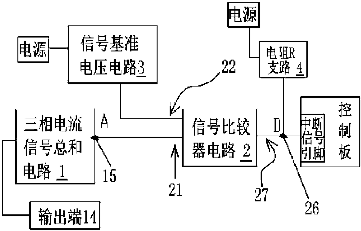
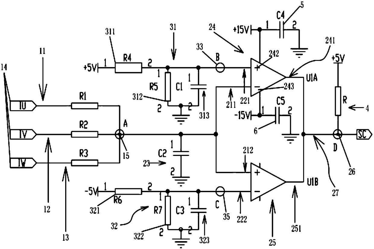
[0024] like figure 1 and 2 As shown, the inverter output short-circuit protection circuit to ground, including:

[0025] Three-phase current signal summation circuit 1, including the first, second and third resistance branches (11, 12 and 13, namely resistance R1 branch, resistance R2 branch and resistance R3 branch shown in the figure) connected in parallel with each other One end of the first, second and third resistance branches (11, 12 and 13) are respec...


PUM


Abstract

The invention discloses an output ground short circuit protection circuit of a frequency converter. The output ground short circuit protection circuit of a frequency converter comprises: a three-phasecurrent signal sum circuit comprising a first resistance branch, a second resistance branch and a third resistance branch connected in parallel; a signal comparator circuit, the connection point is connected to a first comparator voltage input terminal of the signal comparator circuit; a signal reference voltage circuit, wherein one end connected to a power source, and the reference voltage output end connected to a second comparator voltage input terminal of the signal comparator circuit; a resistor R branch, wherein one end connected to a power supply, and the other end is connected to thecomparison output end of the signal comparator to form a level-shifting point, and the level-shifting point is connected with an interrupt signal pin. The output ground short circuit protection circuit of a frequency converter has the beneficial effects that the inverter output can be blocked in response to the output short-circuit current of the inverter in time, thereby avoiding device damage caused by overlong excessive short-circuit current, and the structure is simple, and no other special components need to be added, thereby saving costs and occupying a small space of the frequency converter.

Description

technical field [0001] The invention relates to the technical field of frequency converter protection circuits, in particular to a frequency converter output-to-ground short-circuit protection circuit. Background technique [0002] Inverter output short circuit to ground is a phenomenon often encountered in inverter applications. With the long-term high-temperature use of the motor, the coil in the motor or the power line of the motor will continue to age, and the insulation level will gradually decrease and be broken down, causing the output of the inverter to be short-circuited to the ground. If the output of the inverter is not properly protected, the inverter will be damaged. . At present, domestic inverters rely more on the output-to-ground short-circuit protection of the inverter itself, or rely on the output Hall current sensor or drive optocoupler such as APCL330 and other devices with VCE detection for protection. The above two detection methods have their own defe...

Claims


Application Information

Patent Timeline
IPC IPC(8): H02H7/12
CPCH02H7/1203
Inventor 韦元林
Owner 深圳市默贝克驱动技术有限公司
Learn More